

Ceiling Suspension Mounting#
Step 1
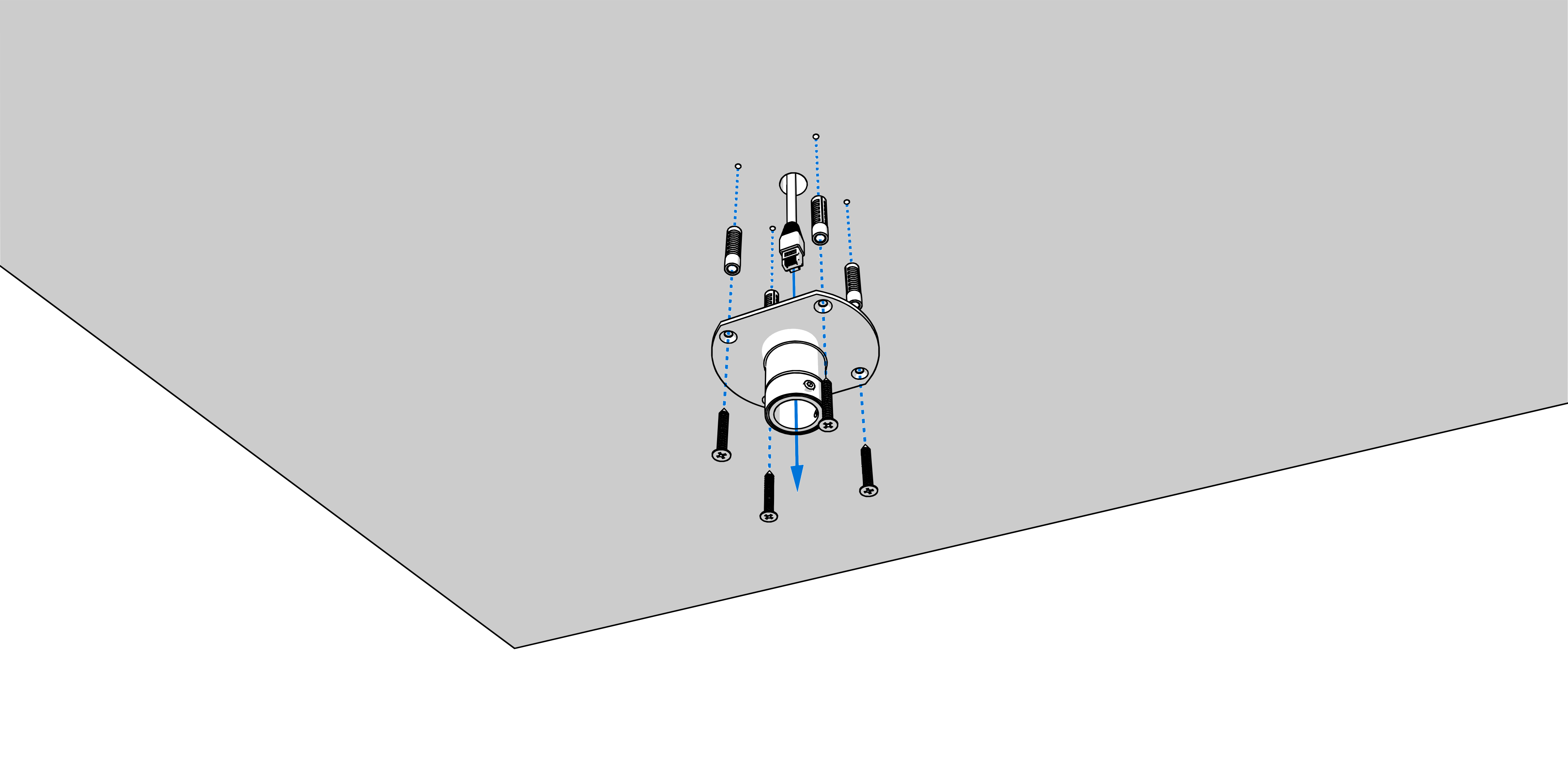
Drill four anchoring holes into a ceiling of a diameter adequate to accommodate supplied wood-type screws with dowels.
Interlace incoming cables through suspension pipe. Fasten the ceiling suspension to ceiling using 4 wood-type screws of 5 mm diameter.
Step 2
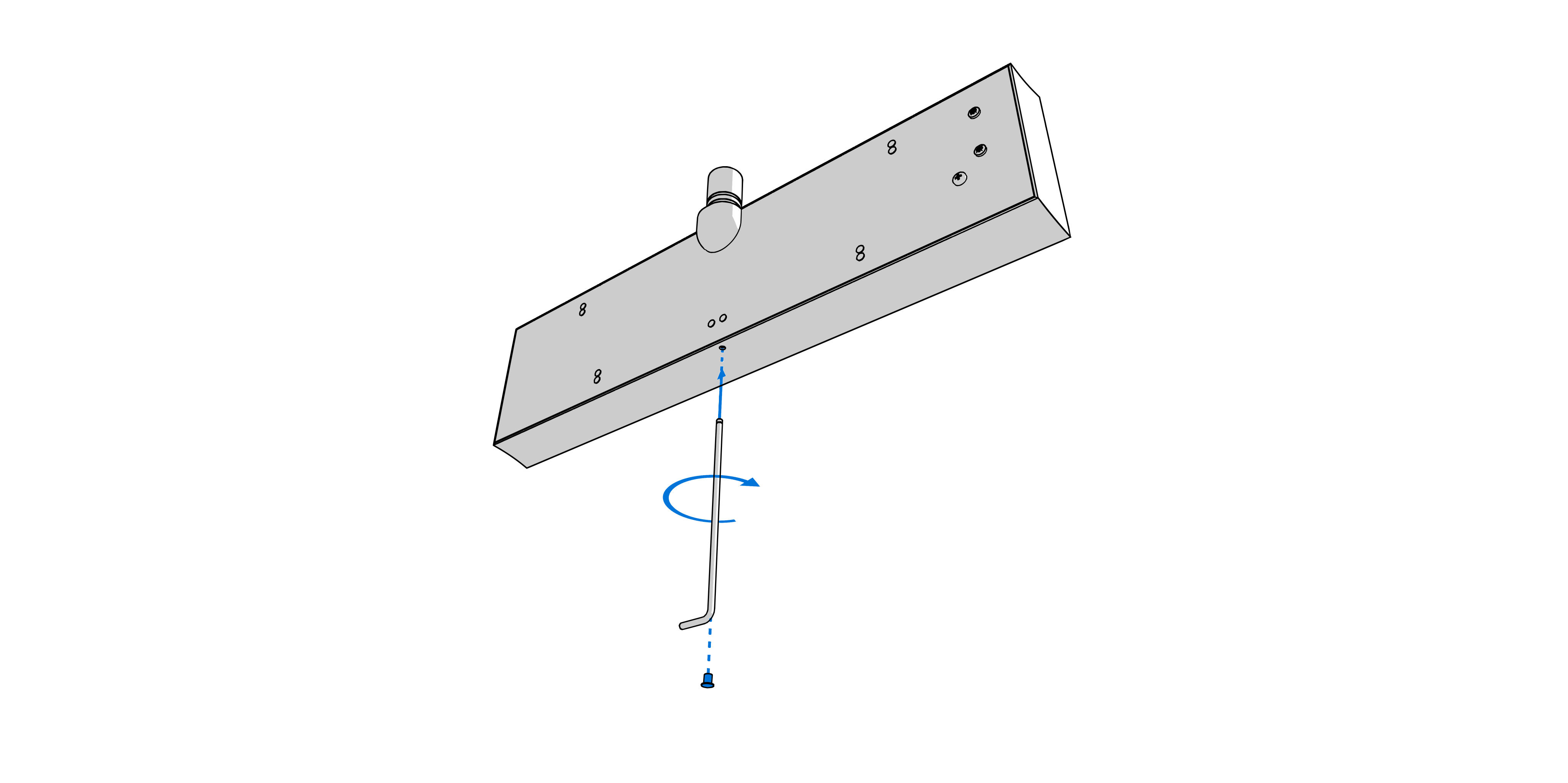
The frame is fixed using two suspensions (above) and two sliding springs (bottom). The frame is locked by frame catch from the bottom side of the frame.
Remove the blind cap from the opening and insert the Allen key into the opening. Turn the key softly in clockwise direction to unlock the frame catch.
Note
Models DC with digit height 57, 75 and 100 the frame catch is unclocked (the screw is already screwed in) when the clock is delivered. The is no need to remove the blind cap and insert the Allen key.
Step 3
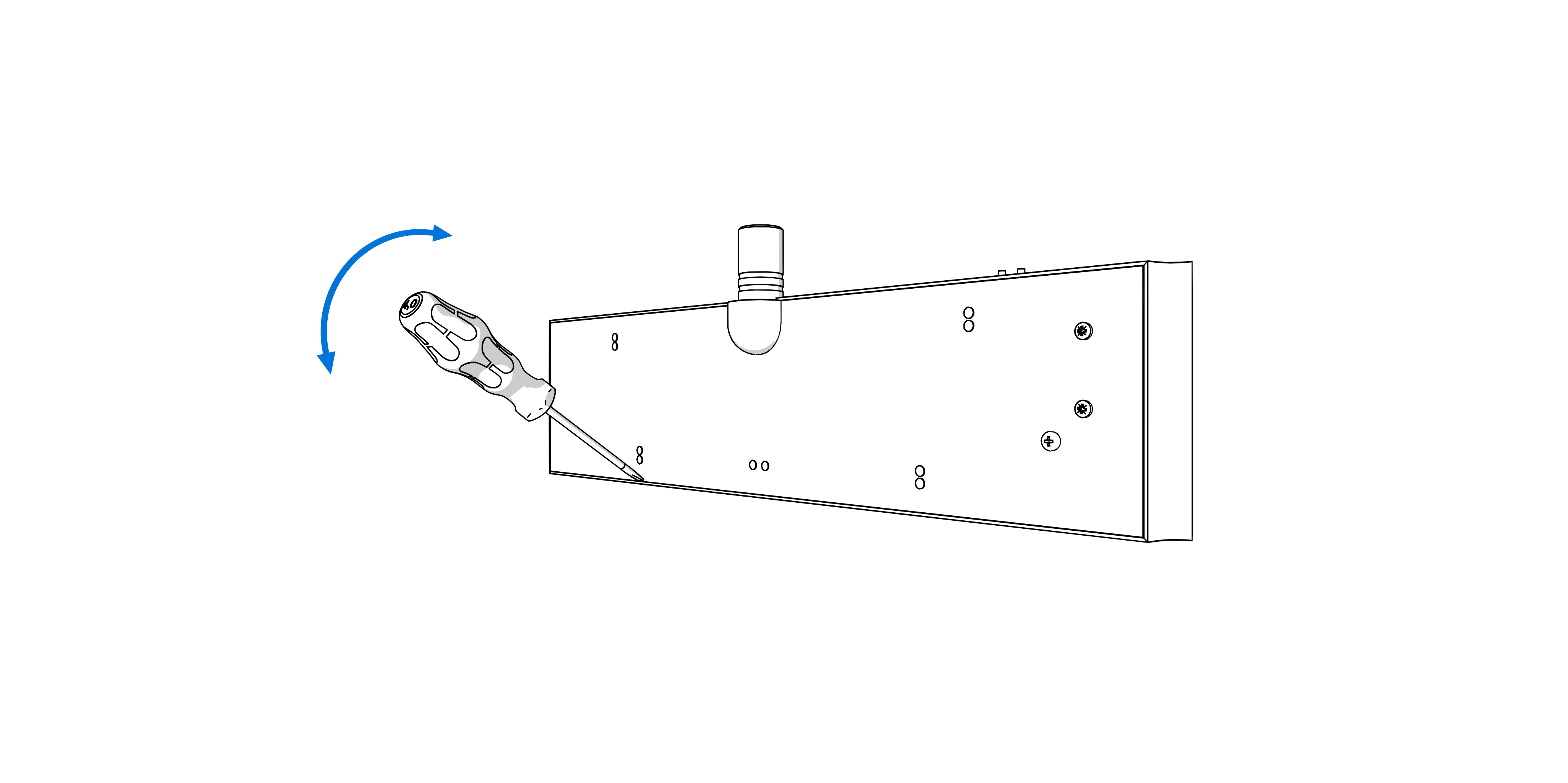
Lift‑off the anchoring plate using a screwdriver inserted in between the sheet and the frame at the sliding spring point on the clock bottom side.
Step 4
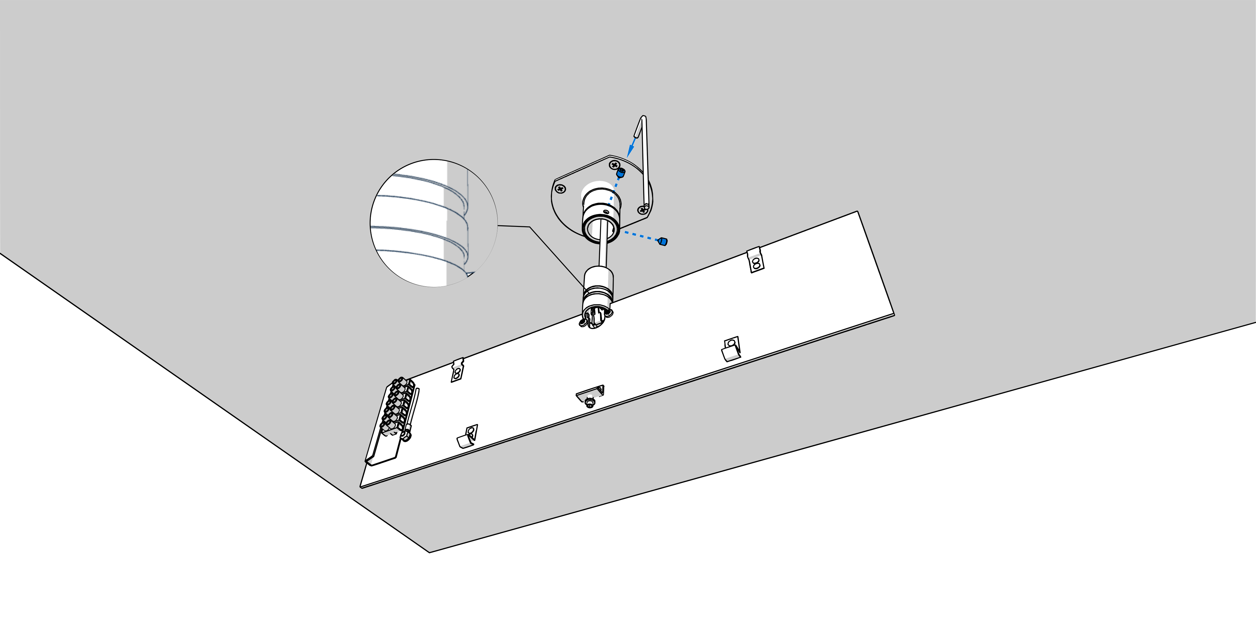
Interlace incoming cables through pipe insert on clock body. Slip-on the clock body onto suspension in a way that screws fit into a groove on pipe insert. Fix the connection by tightening the screw using Allen key No. 3.
Caution
The screws must fit into the upper groove on the pipe insert; otherwise, it will not be possible to mount a display part onto the anchoring plate.
After mounting the display part, it is possible to elevate the clock by securing the anchoring plate in a manner where the screws fit into the lower groove on the pipe insert.
Interlace the incoming conductors through the opening located next to the terminal board and connect the conductors to the terminal board on the anchoring plate, in accordance with the descriptive nameplate. Give an appropriate shape to the conductors of cut them off at a length which does not obstruct the mounting of the clock onto the anchoring plate.
Step 5
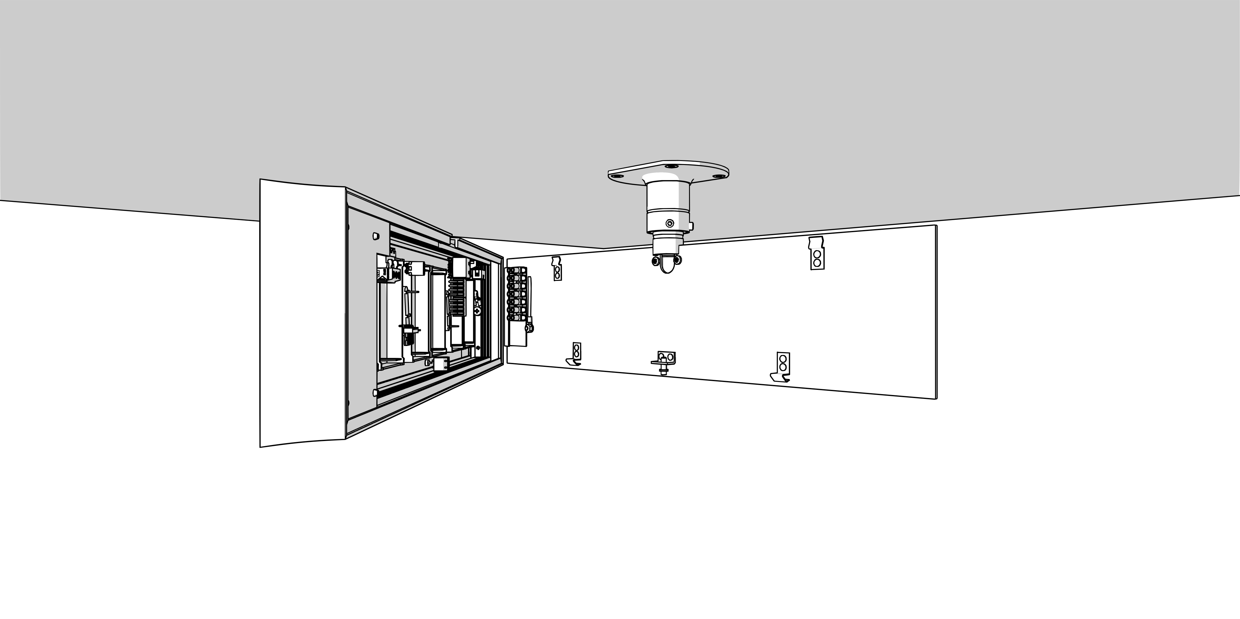
1
See chapter Cable Connection.
Connect the wires of the respective component (e.g., temperature sensor, keyboard, or RS‑485 interface) to the plug‑in terminal connector according to the label next to the terminal.
1
The plug-in terminal connectors are inserted in the terminals.
Insert the plug‑in connector of the respective component (e.g., temperature sensor, keyboard, or RS‑485 interface) into the corresponding terminal on the control board.
Connect the Ethernet cable to the RJ-45 connector, if available.
Caution
Be careful not to swap the terminals. Check the markings of the terminals on the control board.
Connect the interconnecting cables into the corresponding terminals on the clock control PCB.
Caution
For the LGC variant, set the DIP switch according to the used synchronization signal (its position can be found in the Cable Connection chapter, marked with the letter B).
For lines synchronization, keep the DIP switch in its default position.
For all other synchronization signals (DCF, MOBALine, polarized impulse line, IRIG‑B), set the DIP switch to the DCF position.
See the chapter Clock Operation > Non-network Clock Operation for detailed information about connecting the various synchronization sources and receivers.
Step 6
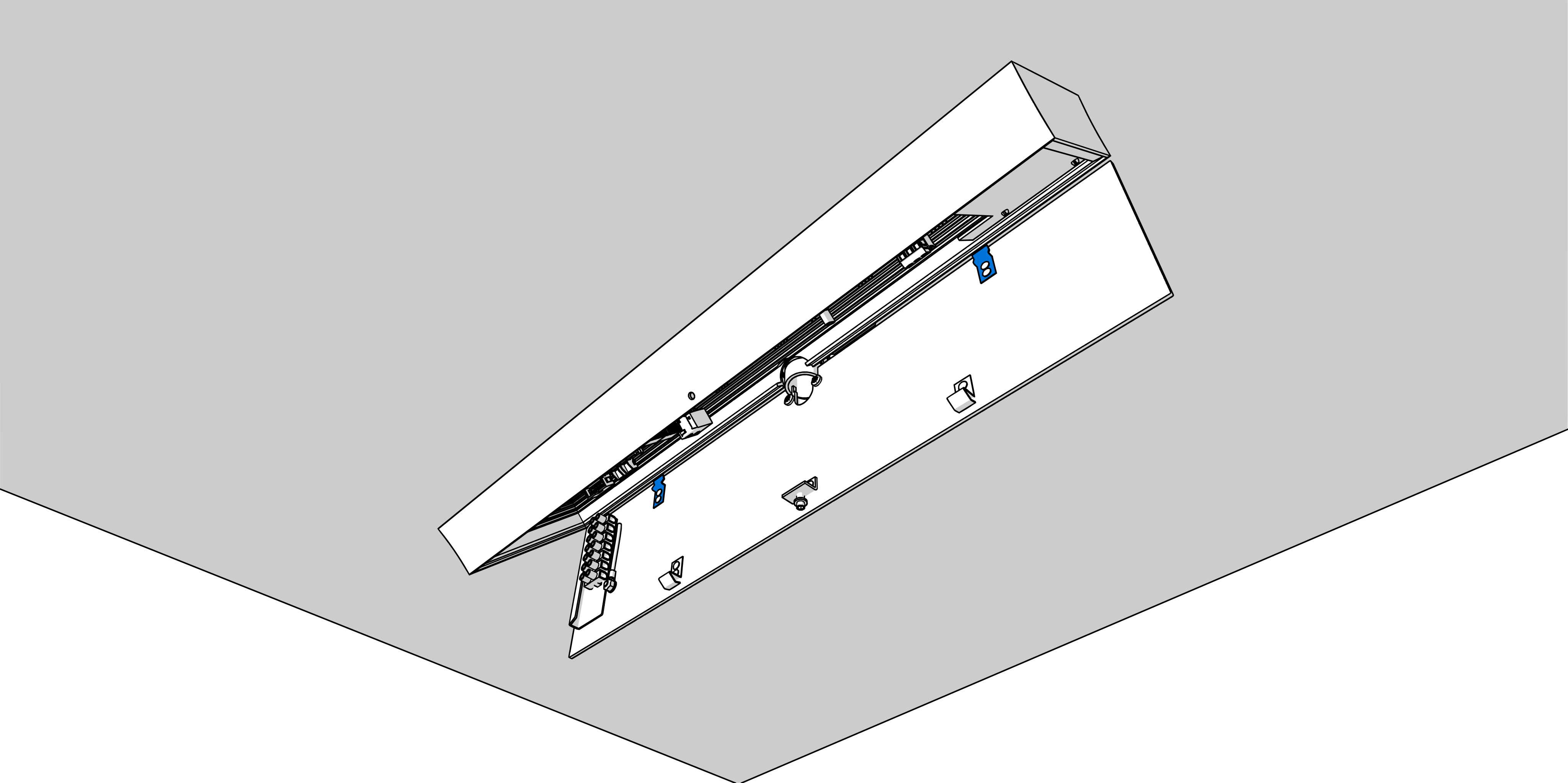
Put the clock opposite to the anchoring plate and suspend it onto the upper springs.
Caution
Care should be taken when placing the cables between the frame edge and the anchoring plate, so an not to nip them.
Step 7
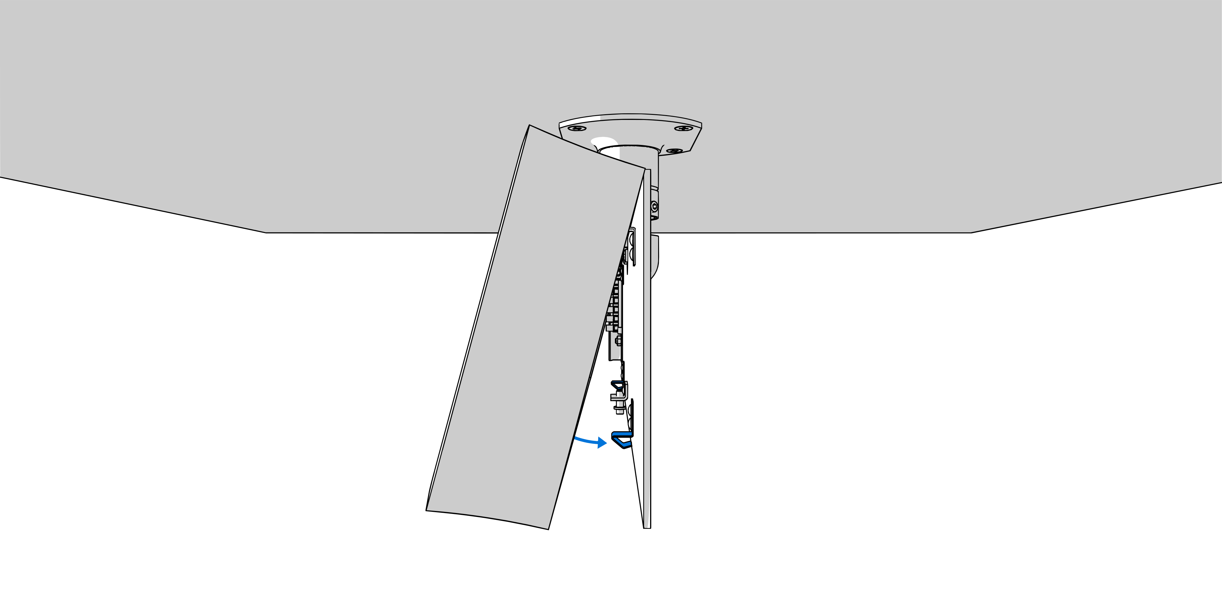
Snap the clock in onto the springs by pushing on the lower part of the frame.
Check whether the anchoring plate on the sides fits exactly into the groove in the clock frame.
Step 8
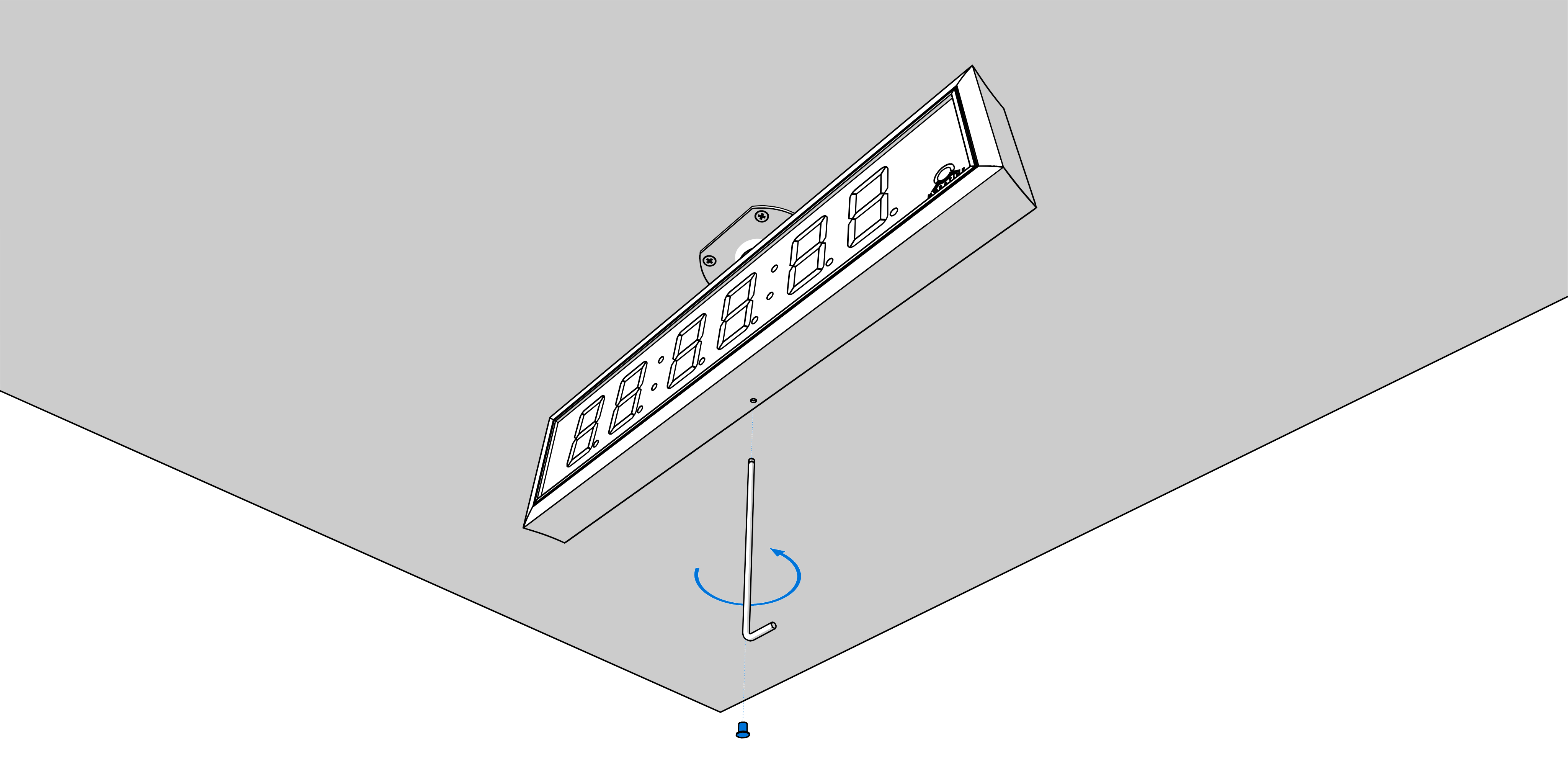
Insert Allen key into the opening on the clock bottom side. Turn the key softly in anticlockwise direction. The frame catch will snap in.
Replace the blind cap on the opening.
Hint
To dismount the clock, use reverse procedure.