

Ceiling Suspension Mounting#
Step 1
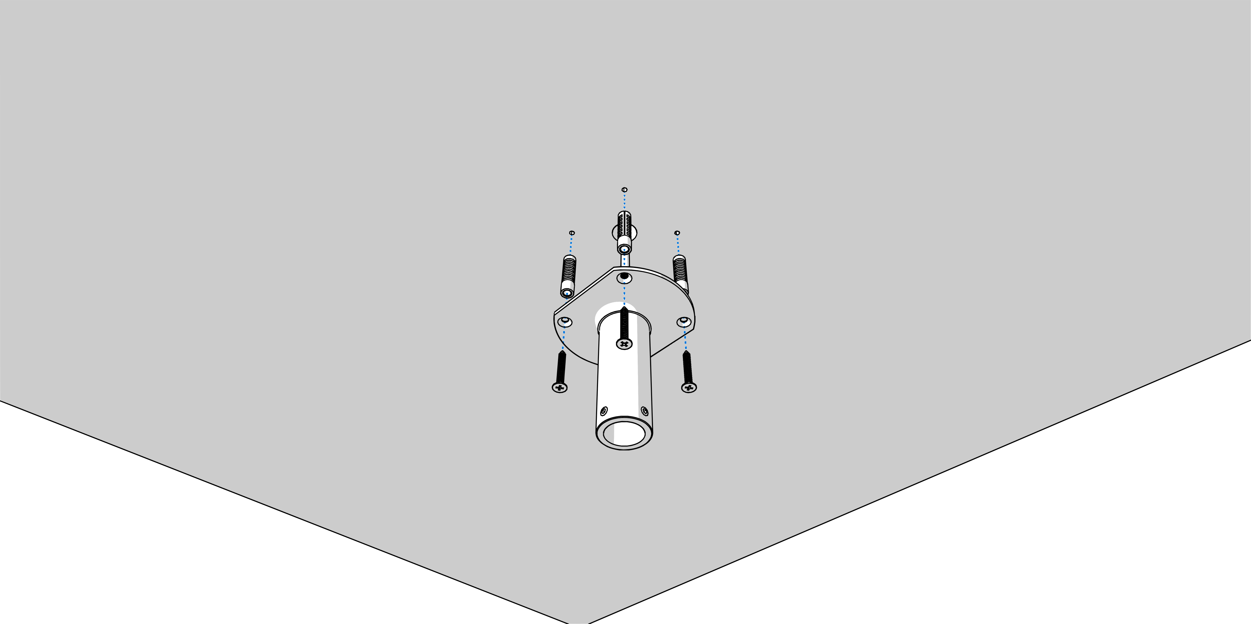
Drill four anchoring holes into a ceiling of a diameter adequate to accommodate supplied wood-type screws with dowels.
Interlace incoming cables through suspension pipe. Fasten the ceiling suspension to ceiling using 4 wood-type screws of 5 mm diameter.
Step 2
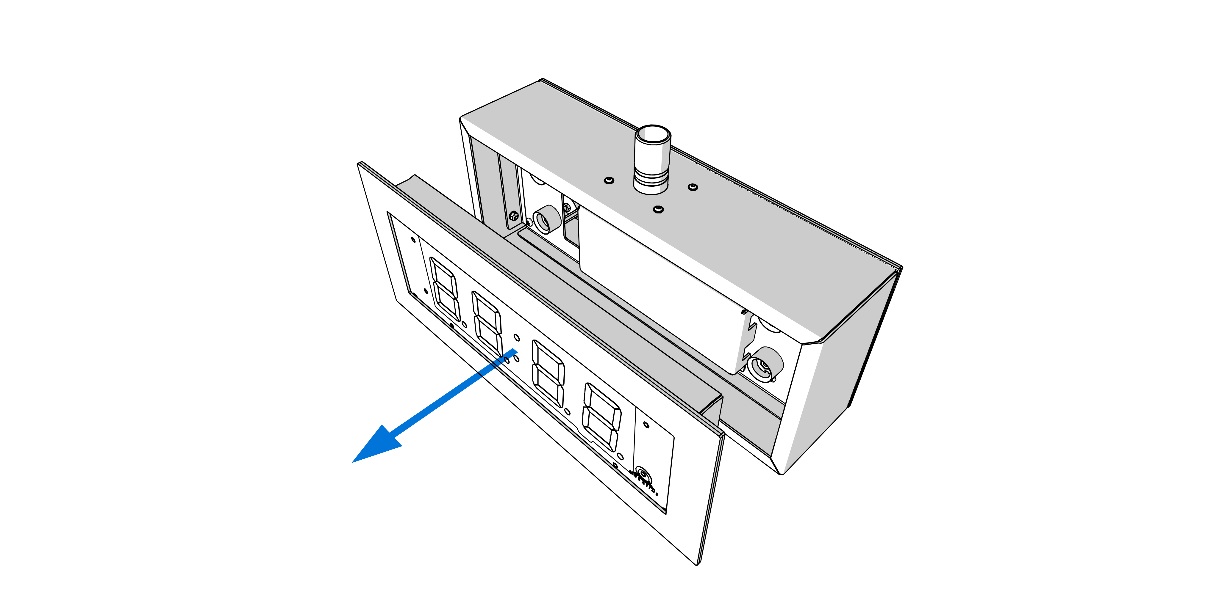
The clock consists of three parts:
Visible front stainless steel panel with display serving as control module (with jacks to connect powering cables and connection terminals)
Stainless steel body with connecting terminal block
Visible rear stainless steel panel with display serving as display module (with terminal for the connection of the interconnecting cable)
Control module and stainless steel body are held together by neodymium magnets. Display module is fixed by srews and is not necessary to dismount it.
Remove the front panel from the clock body. The panel is held by magnets, relatively high force required to remove it.
Disconnect the interconnecting cables by decoupling the terminals on the control PCB.
Disconnect the earth wire connecting the clock body to the front panel.
Step 3
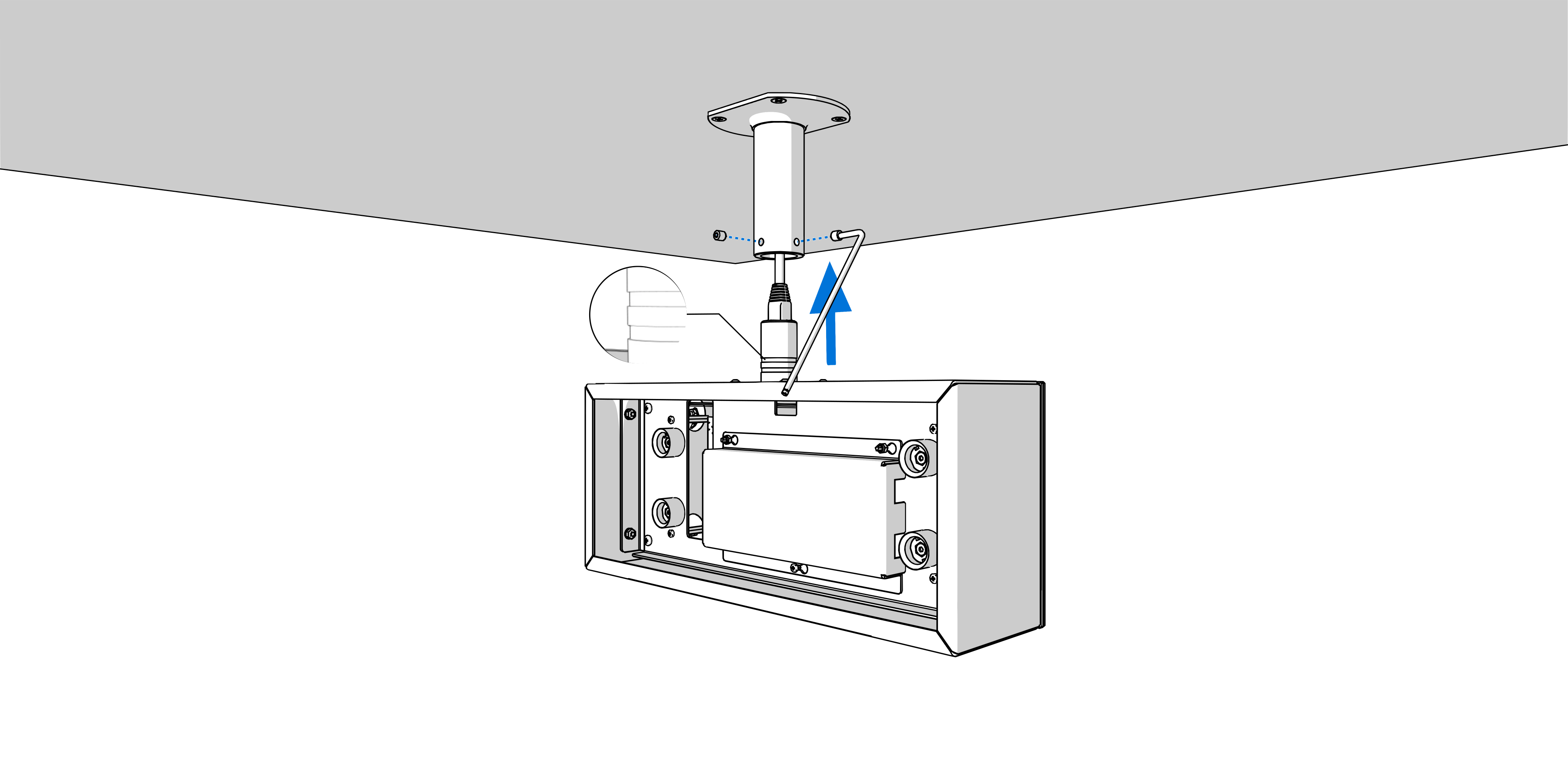
Interlace incoming cables through pipe insert on clock body. Slip-on the clock body onto suspension in a way that screws fit into a groove on pipe insert. Fix the connection by tightening the screw using Allen key No. 3.
Step 4
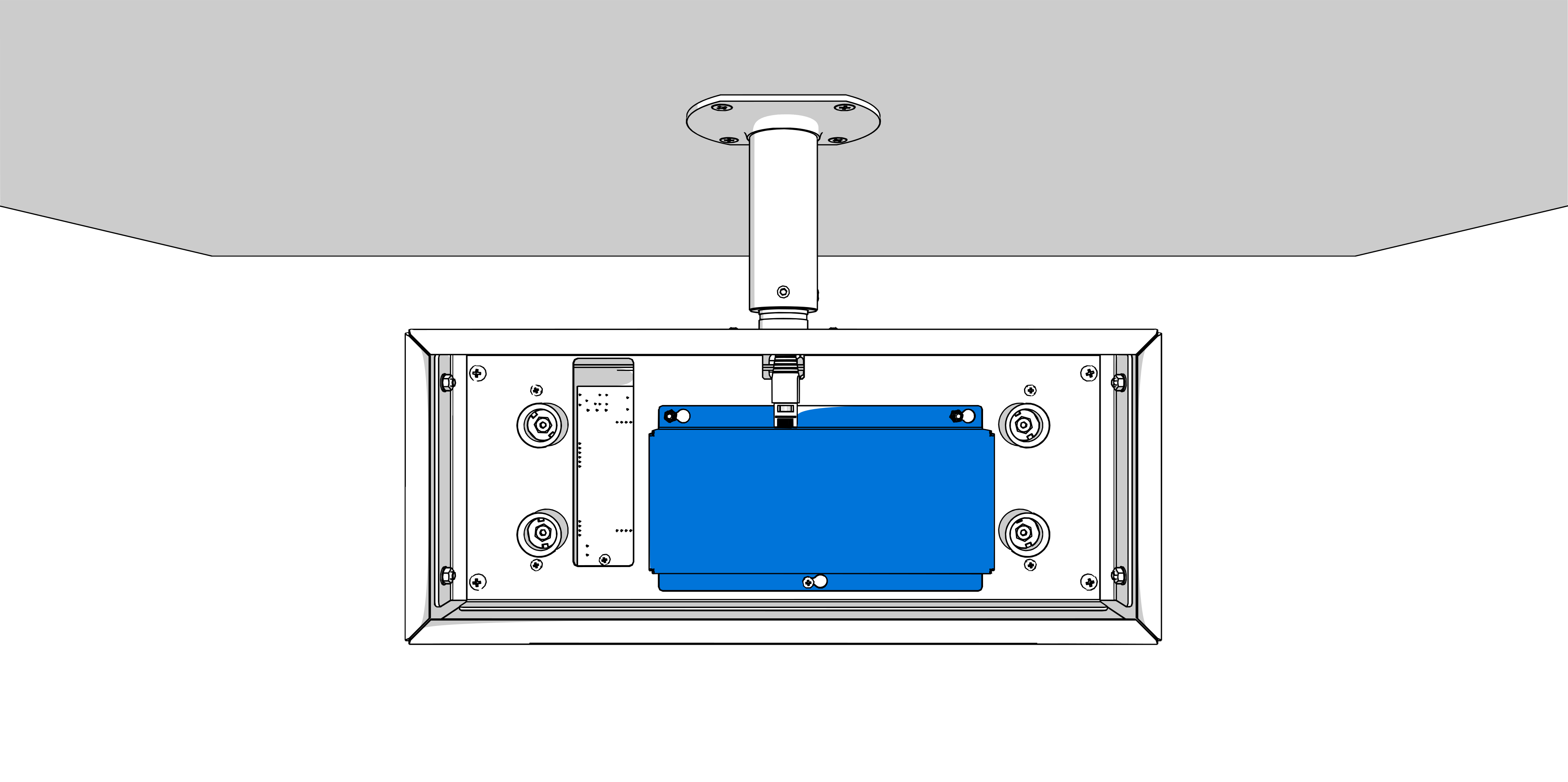
For mains-powered clock, loosen the screw on the underside of the 230 VAC terminal cover and remove the cover. Unscrew the cable clamp.
Step 5
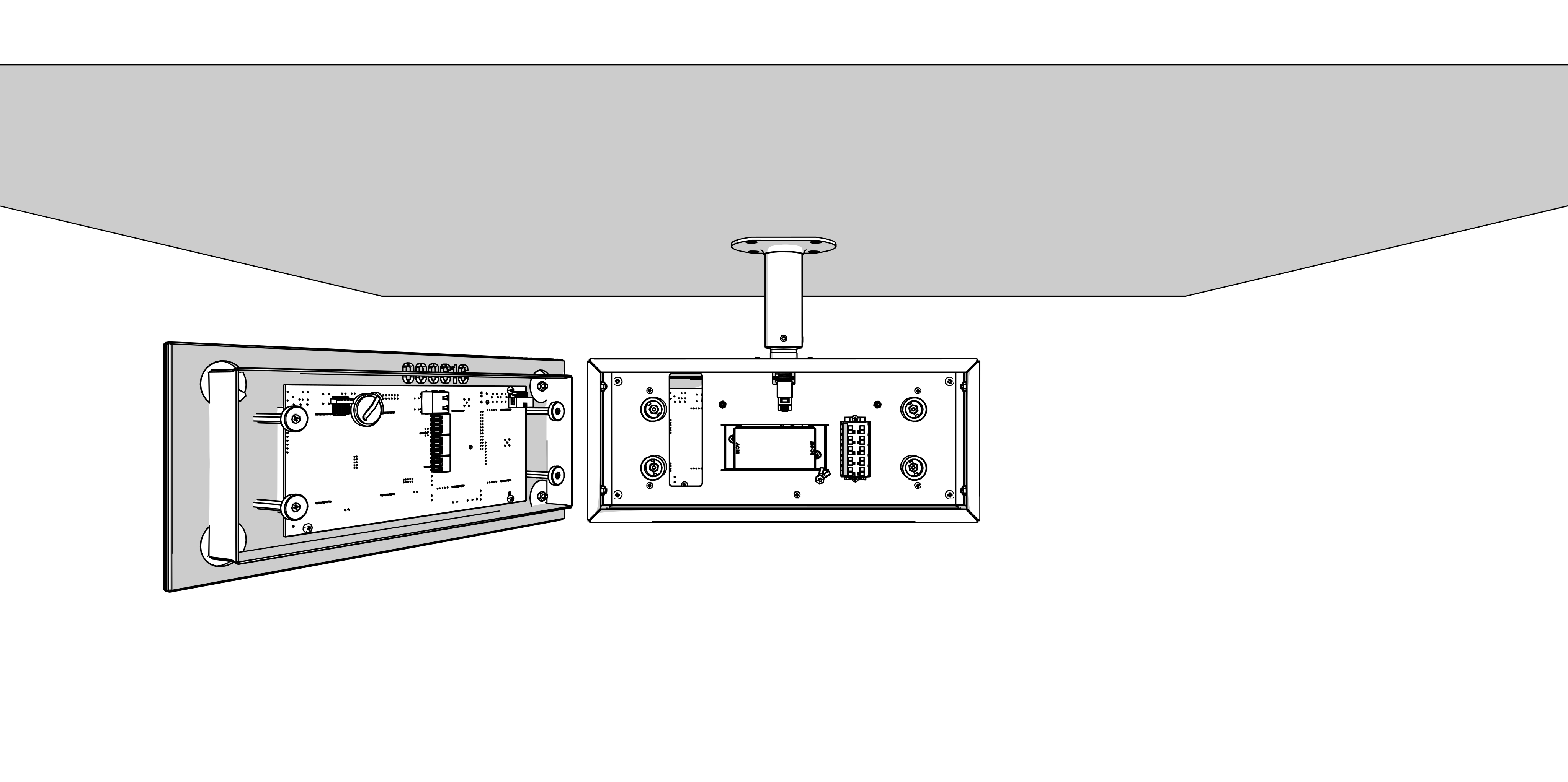
1
See chapter Cable Connection.
For mains‑powered clocks, connect the supply conductors according to the labels located on the terminals of the power module.
Shape or shorten the conductors so that their routing does not obstruct proper positioning and securing of the clock.
Mount the 230 VAC terminal cover back and secure it by tightening the screw on the underside of the cover.
For PoE‑powered clocks, connect a PoE‑enabled Ethernet cable to the RJ‑45 connector on the control board.
Use a PoE switch port or PoE injector that provides the required PoE power.
Connect the wires of the respective component (e.g., temperature sensor, keyboard, or RS‑485 interface) to the plug‑in terminal connector according to the label next to the terminal.
1
The plug-in terminal connectors are inserted in the terminals.
Insert the plug‑in connector of the respective component (e.g., temperature sensor, keyboard, or RS‑485 interface) into the corresponding terminal on the control board.
Connect the Ethernet cable to the RJ-45 connector, if available.
Caution
Be careful not to swap the terminals. Check the markings of the terminals on the control board.
Connect the interconnecting cables into the corresponding terminals on the clock control PCB.
Reconnect the grounding conductor back.
Caution
For the LGC variant, set the DIP switch according to the used synchronization signal (its position can be found in the Cable Connection chapter, marked with the letter B).
For lines synchronization, keep the DIP switch in its default position.
For all other synchronization signals (DCF, MOBALine, polarized impulse line, IRIG‑B), set the DIP switch to the DCF position.
See the chapter Clock Operation > Non-network Clock Operation for detailed information about connecting the various synchronization sources and receivers.
Step 6
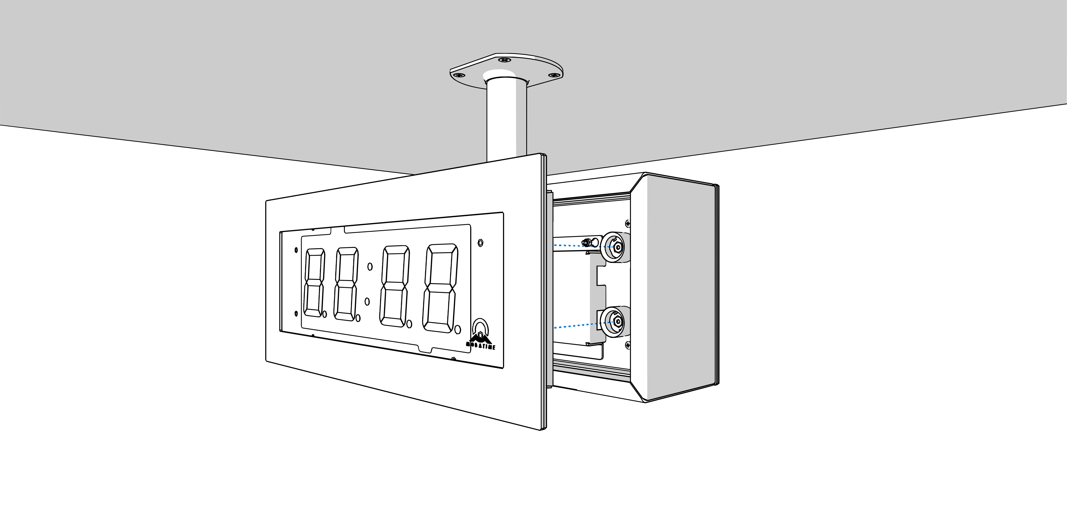
Put the front panel into the clock body. Check the cables to prevent them from being pinched between the back of the front panel and the clock body.