Ceiling Suspension Mounting#
Note
Displayed numbers do not correspond with step numbers below.
Double-sided clock consists of two parts - MASTER display (this part encompasses a terminal to connect supply voltage and synchronization source) and SLAVE display (this part encompasses a terminal for connection of interconnecting cable). Both clock parts are interconnected via 10-core flat cable.
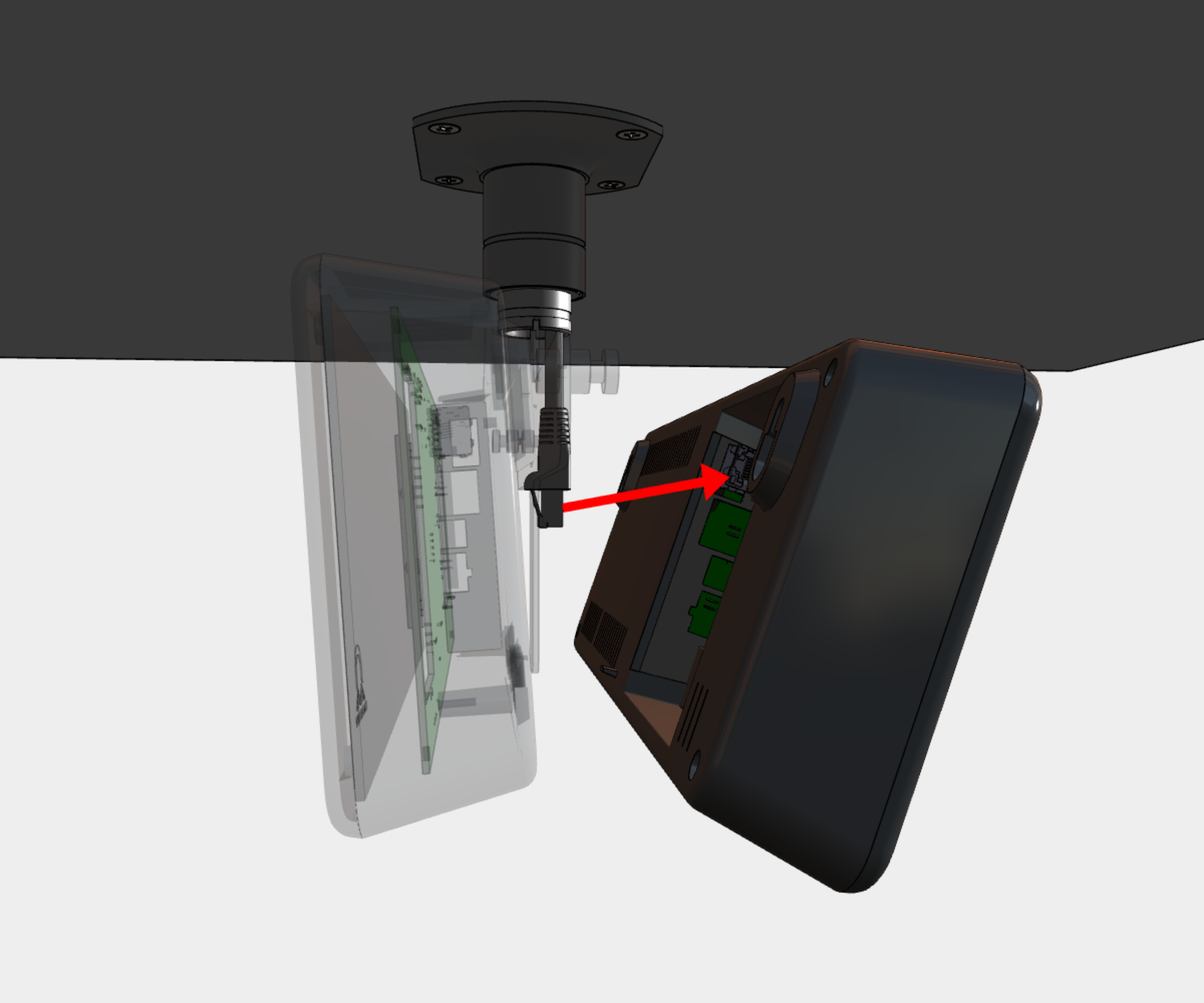
Connect the 10-core interconnecting cable into corresponding plug on clock control PCB of the SLAVE display.
Warning
The cable must never be connected or disconnected while power on MASTER display is on.
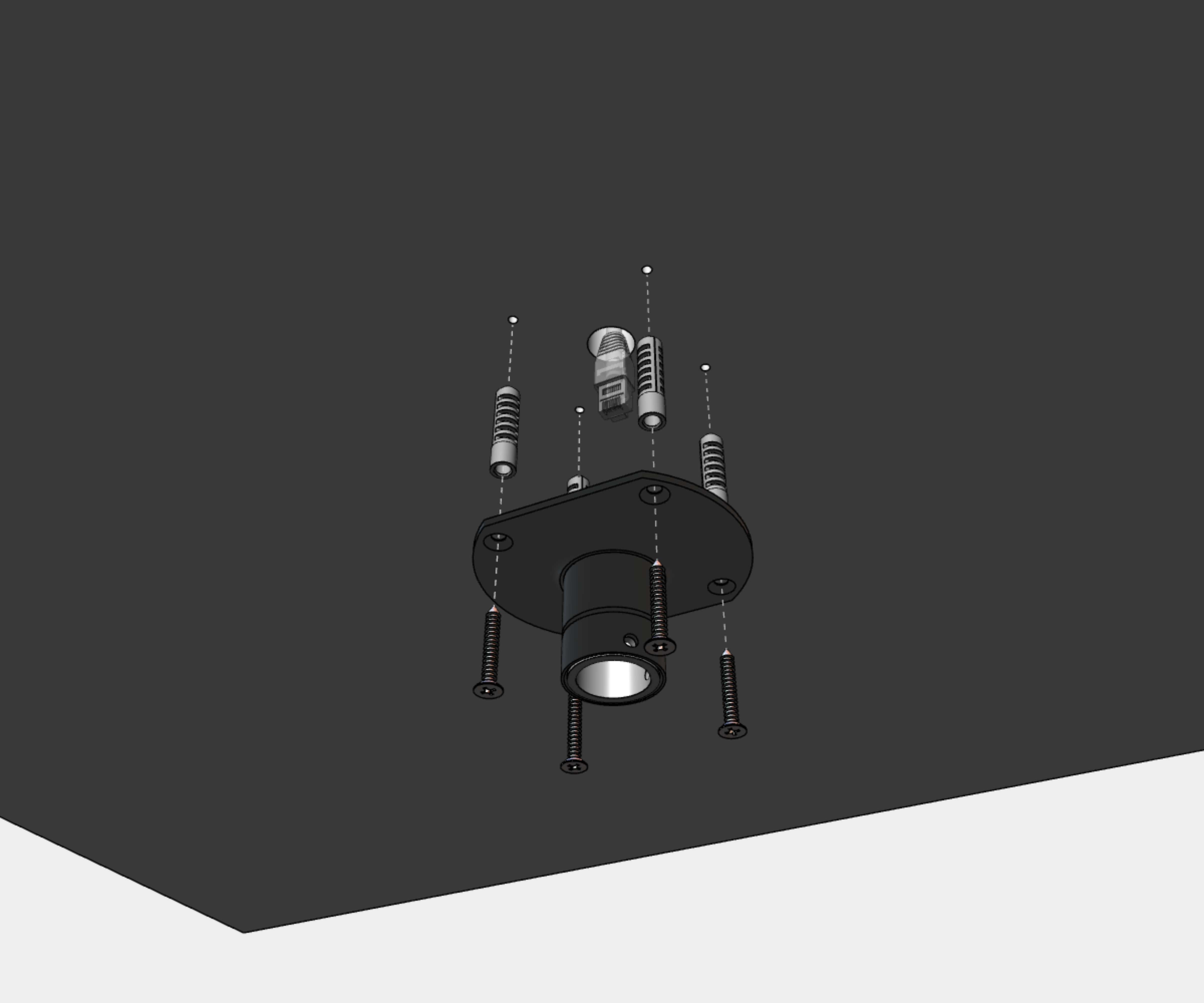
Step 1 – Secure the Ceiling Suspension Pipe to the Ceiling#
Drill four anchoring holes into a ceiling of a diameter adequate to accommodate supplied wood-type screws with dowels.
Interlace incoming cables through suspension pipe. Secure the ceiling suspension to ceiling using 4 wood-type screws of 5 mm diameter.
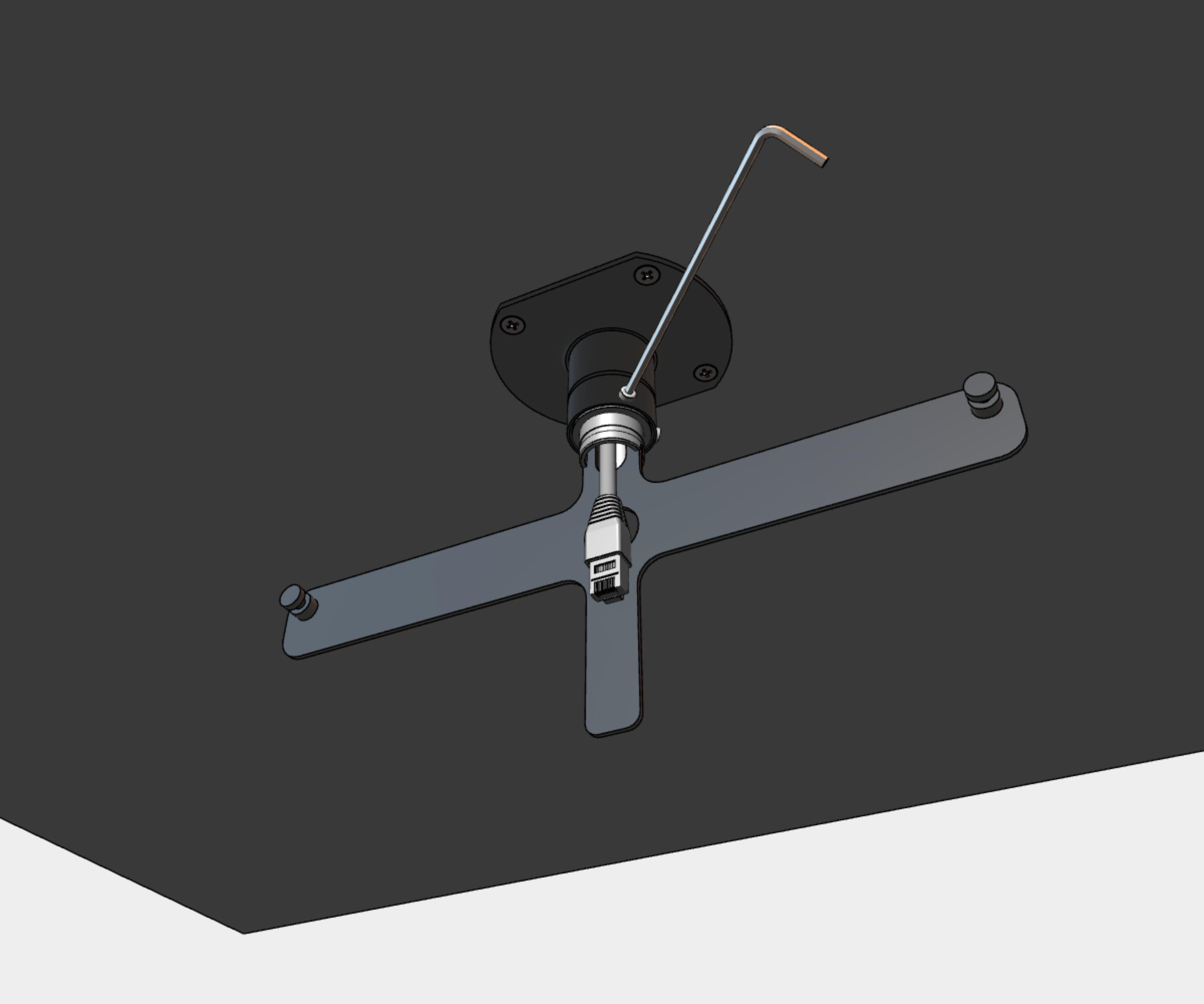
Step 2 – Secure the Anchor Plate to Ceiling Suspension Pipe#
Interlace incoming cables through pipe insert on anchoring plate. Slip-on the plate onto suspension in a way that screws fit into upper groove on pipe insert. Secure the connection by tightening the screws using Allen key No. 3.
Note
The screws must fit into the upper groove on the pipe insert; otherwise, it will not be possible to mount a display part onto the anchoring plate.
After mounting the display part, it is possible to elevate the clock by securing the anchoring plate in a manner where the screws fit into the lower groove on the pipe insert.
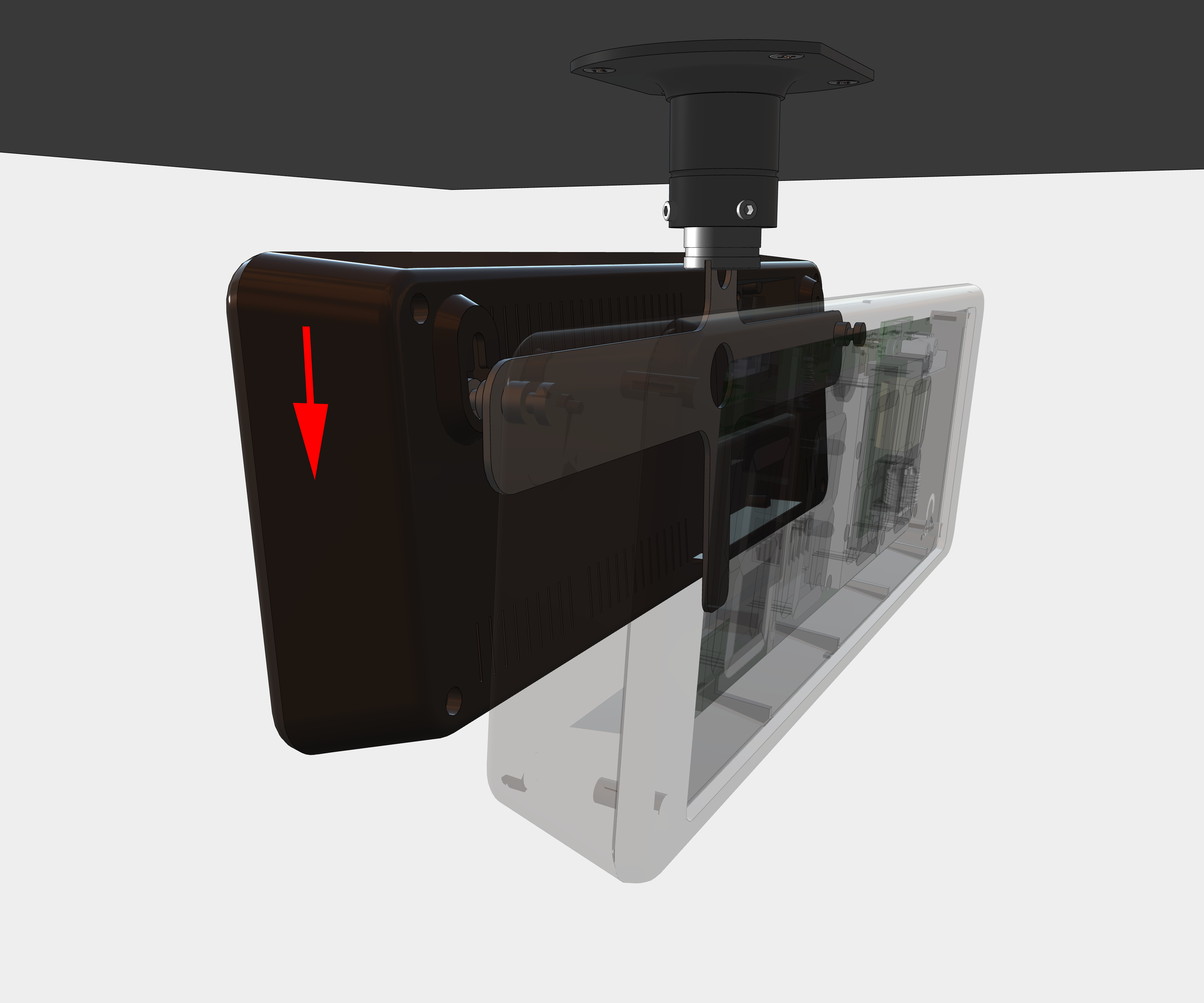
Step 3 – Hang the SLAVE Display#
Hang the SLAVE display onto the anchoring plate.
Hint
If the clock has to be tilted down slightly, cut the supporting element on bottom of back side accordingly.
Step 4 – Prepare & Connect Cables#
Shorten all incoming cables appropriately, connect them to MASTER display.
Mount a wide 2-pin connector to incoming powering cable.
Mount a 2-pin connector to synchronization signal cable or crimp RJ45 modular connector to incoming Ethernet cable.
Connect all interconnecting cables into corresponding connectors in back side recess.
Interconnect both displays with 10-core cable.
1
See Cable Connection chapter.
Caution
For use of a DCF/GPS receiver, make sure to switch the DIP switch accordingly. For details, refer to the Cable Connection chapter > Dismounting the Front Plexiglass chapter.
Navigate to Clock Operation chapter > Non-Network Clock Operation chapter to get detailed info about connection of various synchronization sources and receivers.
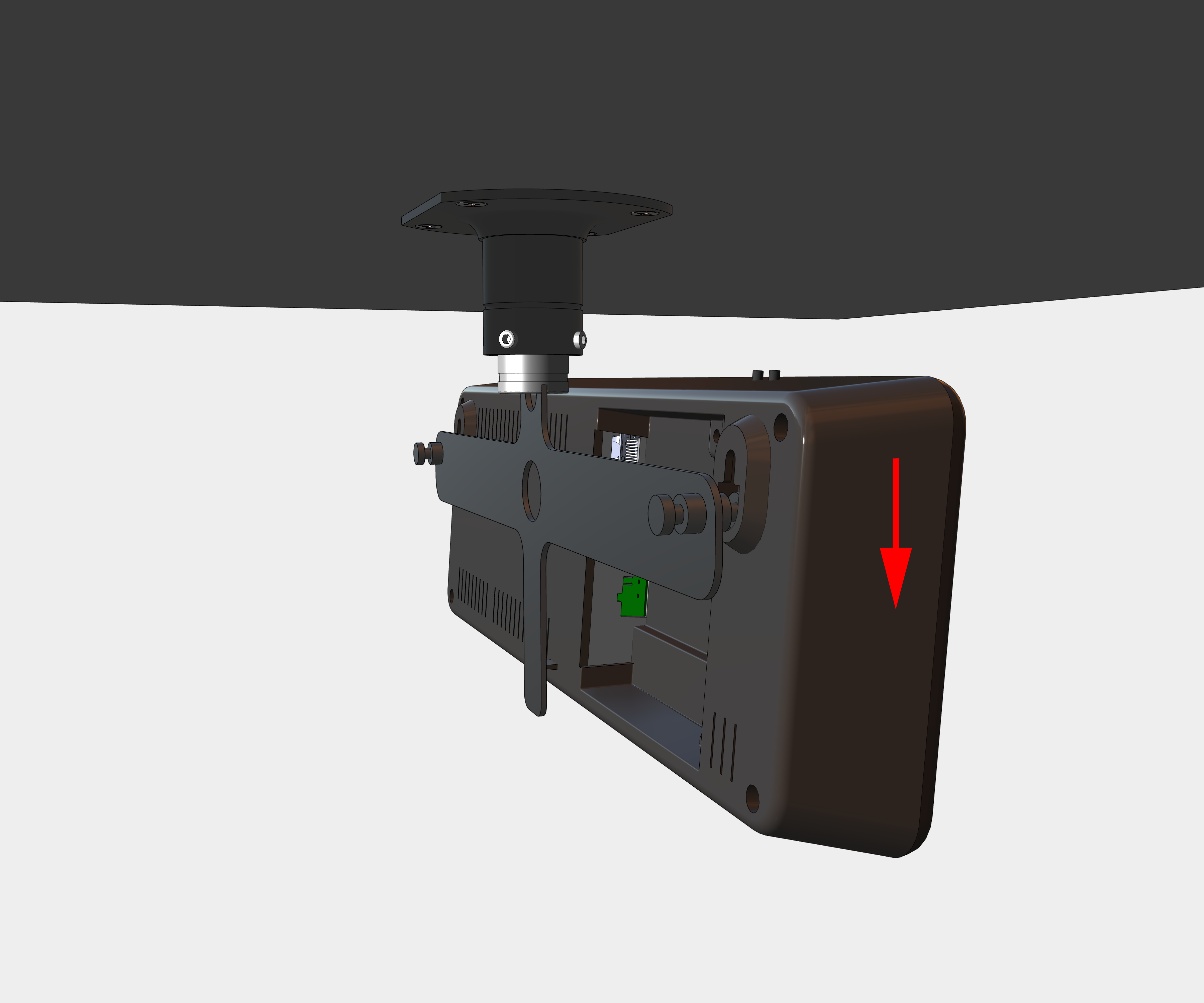
Step 5 – Hang the MASTER Display#
Hang the MASTER display onto the anchoring plate.
Hint
If the clock has to be tilted down slightly, cut the supporting element on bottom of back side accordingly.