Ceiling Suspension Mounting#
Note
Displayed numbers do not correspond with step numbers below.
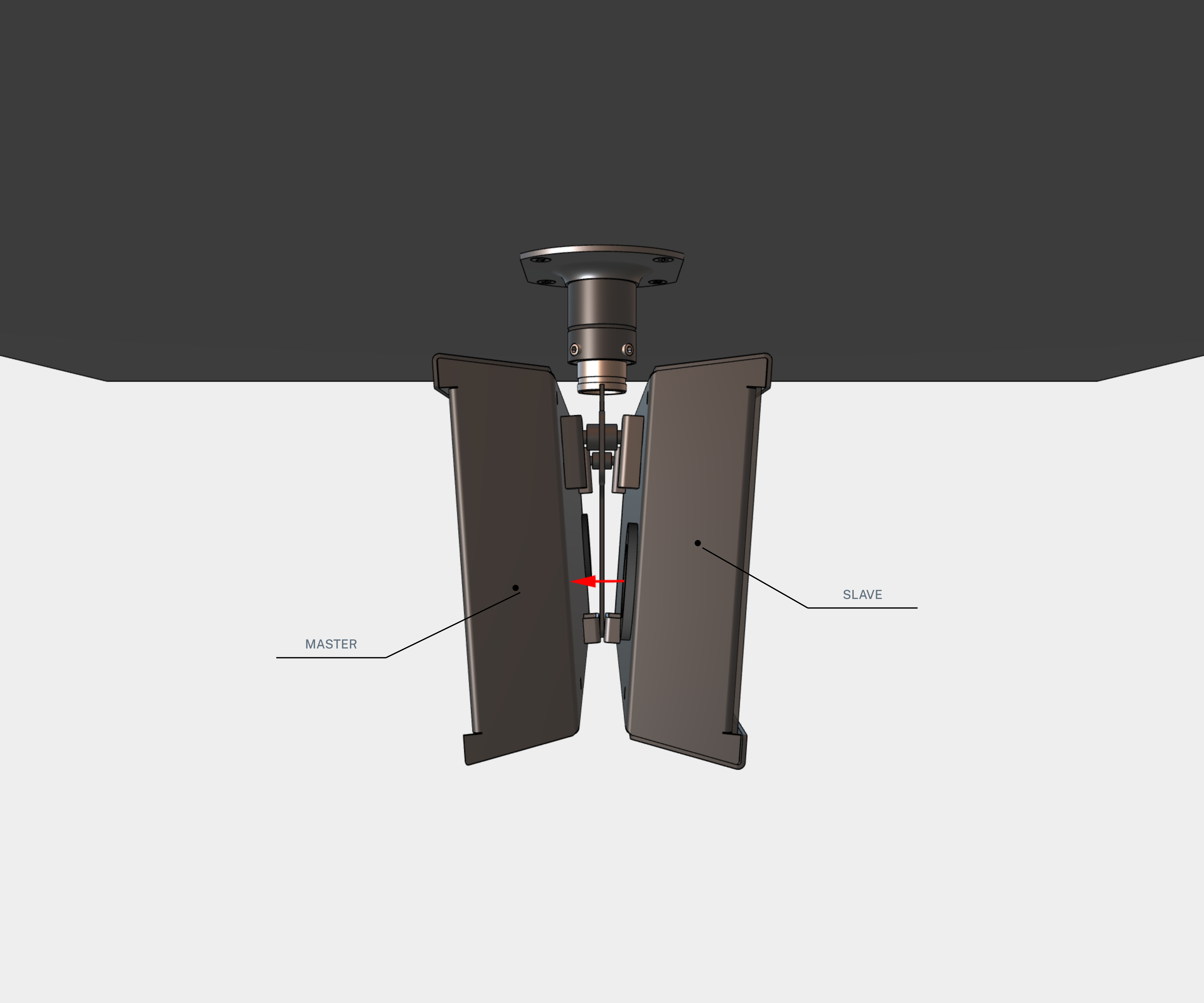
Double-sided clock consists of two parts - MASTER display (this part encompasses a terminal to connect supply voltage and synchronization source) and SLAVE display (this part encompasses a terminal for connection of interconnecting cable). Both clock parts are interconnected via 10-core flat cable.
Connect the 10-core interconnecting cable into corresponding plug on clock control PCB of the SLAVE display.
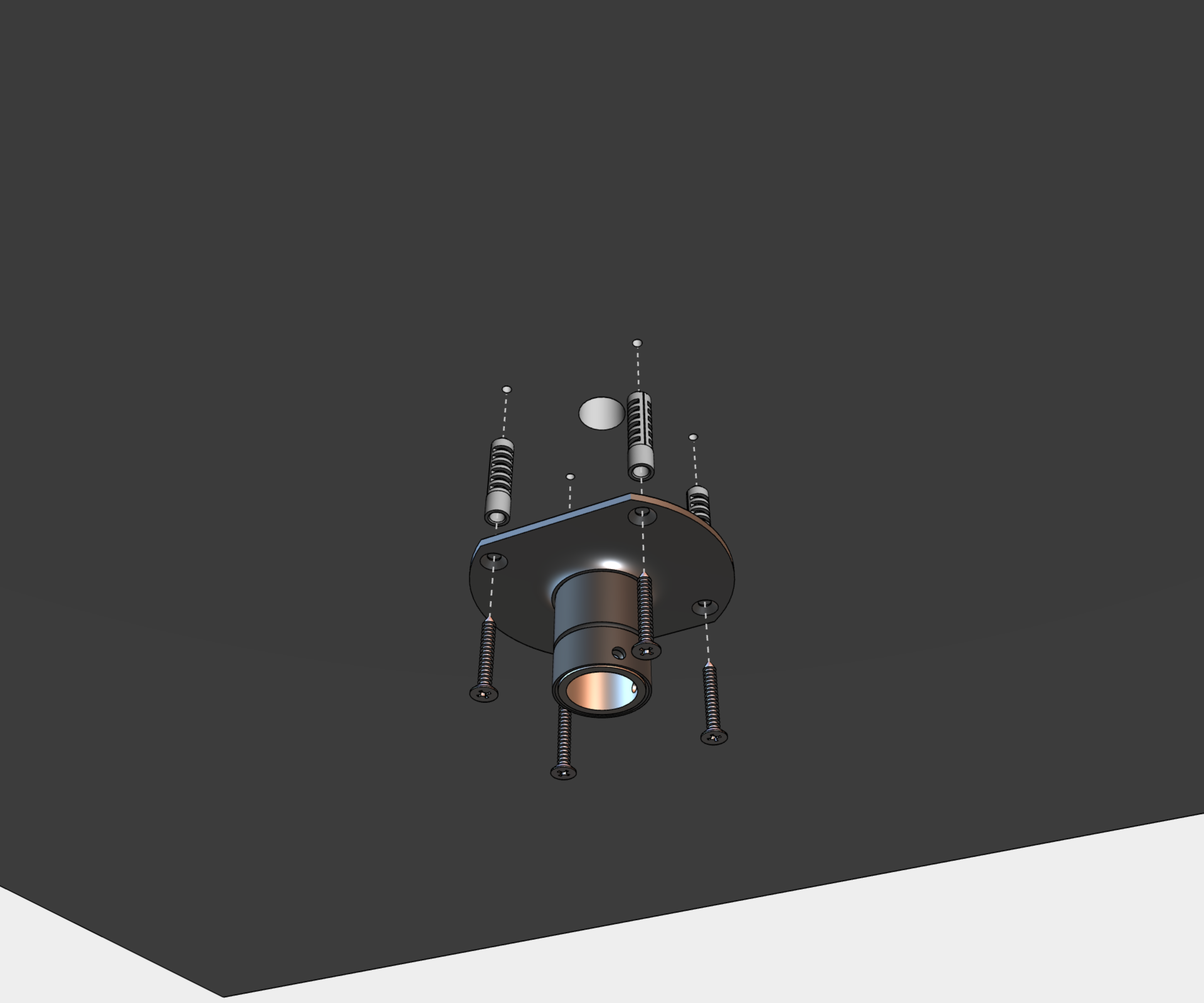
Step 1 – Secure the Ceiling Suspension Pipe to the Ceiling#
Drill four anchoring holes into a ceiling of a diameter adequate to accommodate supplied wood-type screws with dowels.
Interlace incoming cables through suspension pipe. Fasten the ceiling suspension to ceiling using 4 wood-type screws of 5 mm diameter.
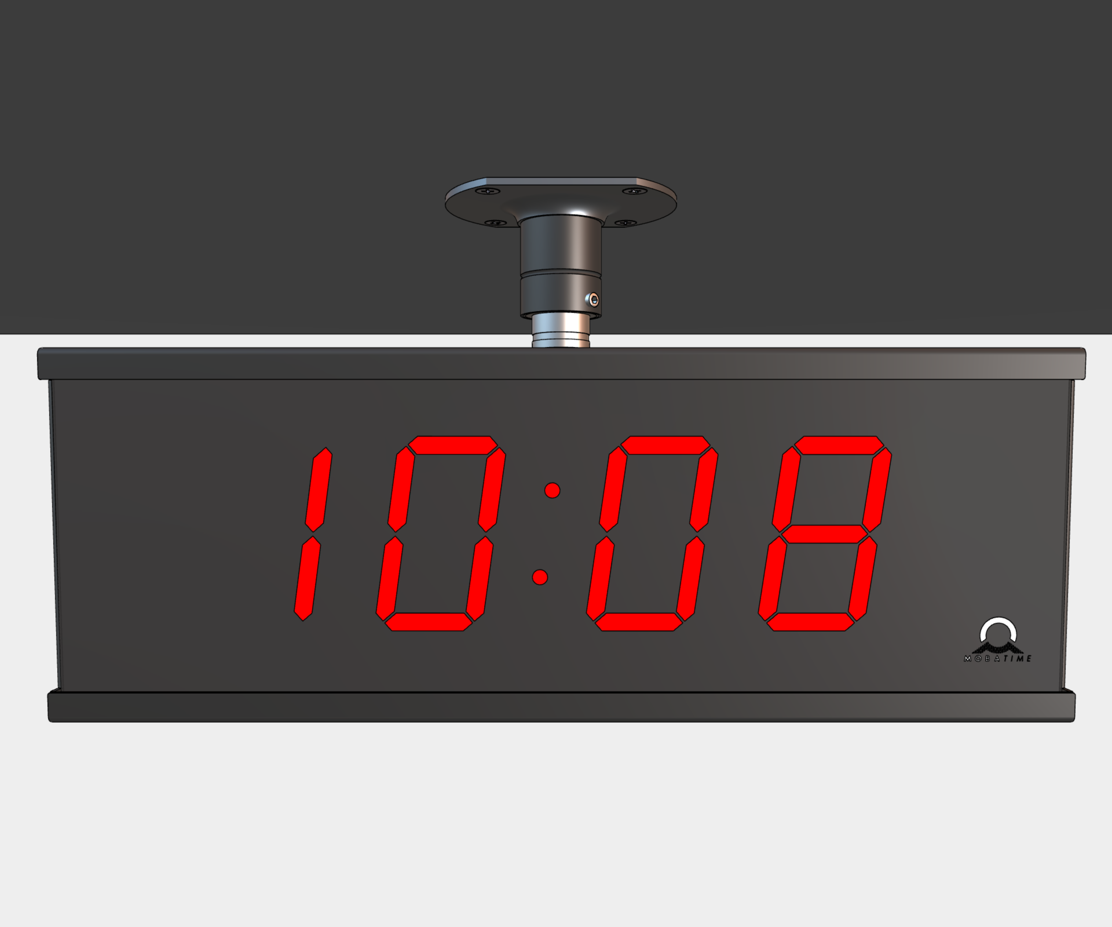
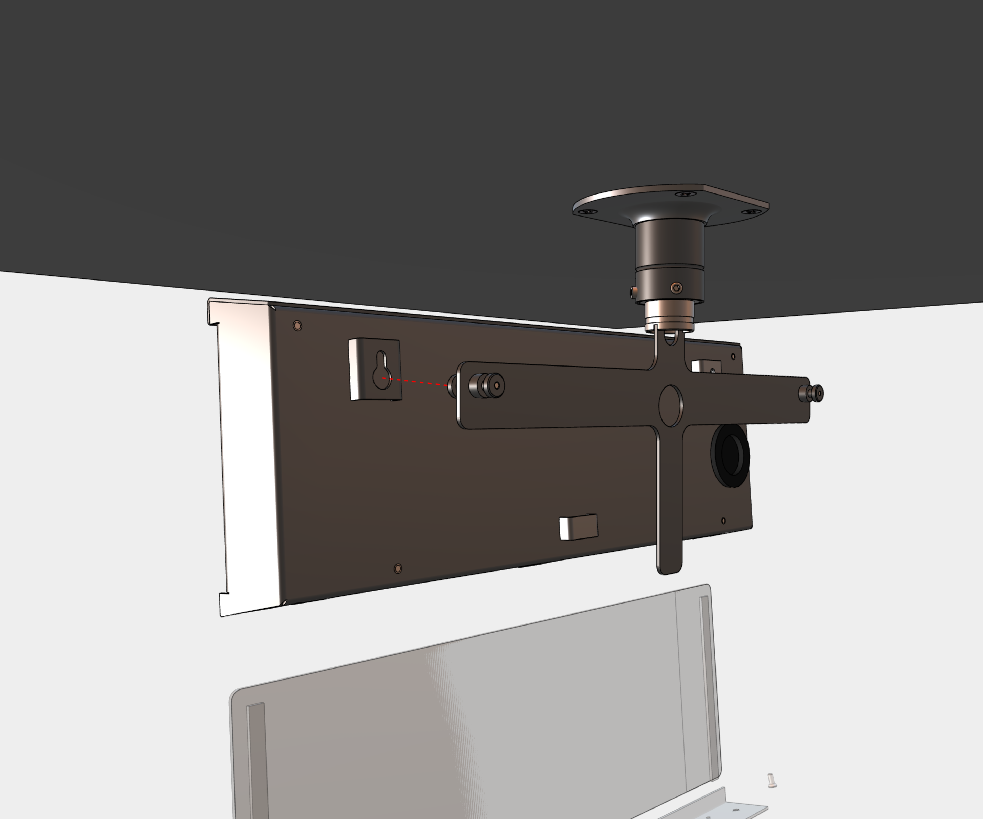
Step 2 – Secure the Anchor Plate to Ceiling Suspension Pipe#
Interlace incoming cables through pipe insert on anchoring plate. Slip-on the plate onto suspension in a way that screws fit into upper groove on pipe insert. Fix the connection by tightening the screw using Allen key No. 3.
Note
The screws must fit into the upper groove on the pipe insert; otherwise, it will not be possible to mount a display part onto the anchoring plate.
After mounting the display part, it is possible to elevate the clock by securing the anchoring plate in a manner where the screws fit into the lower groove on the pipe insert.

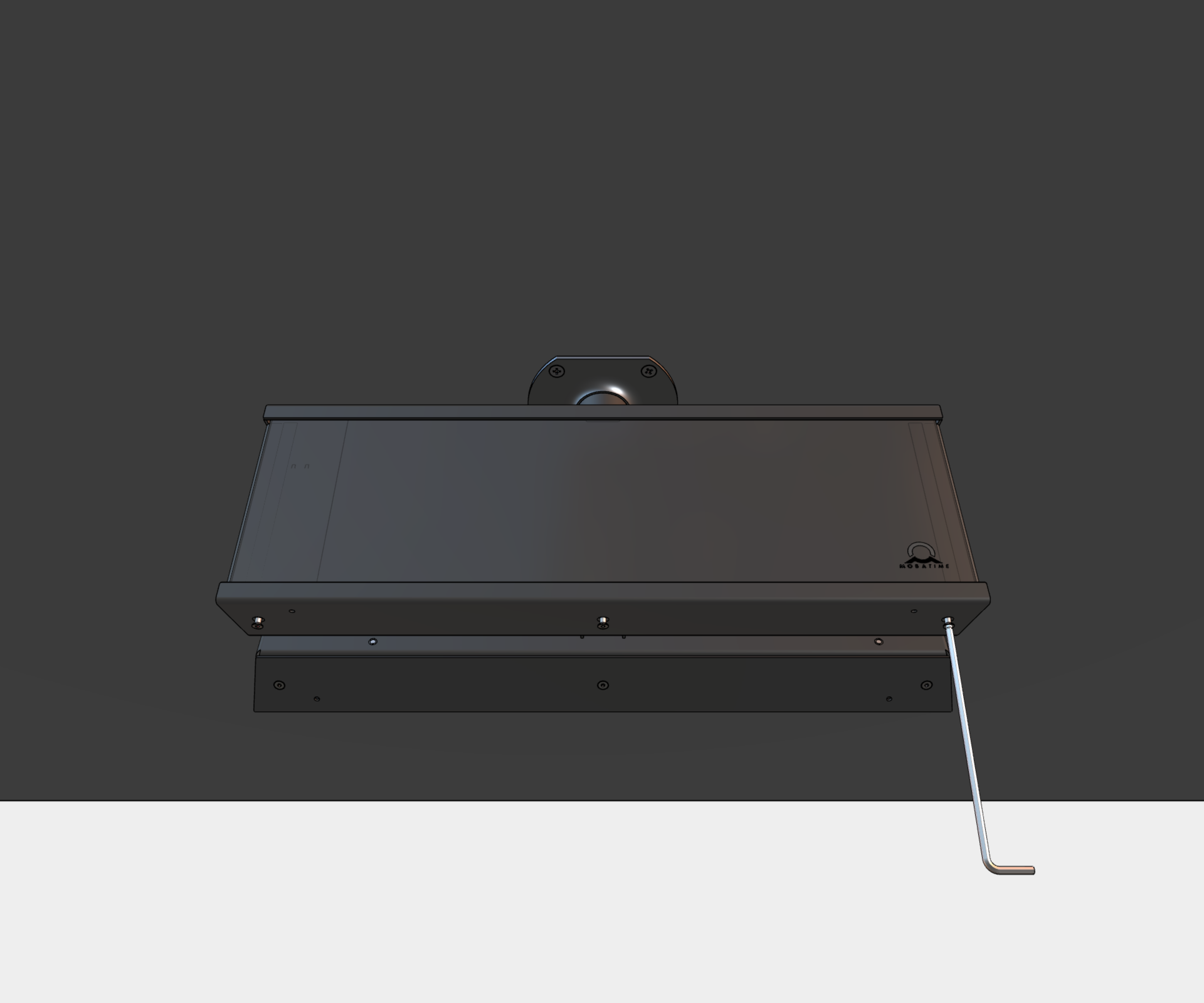
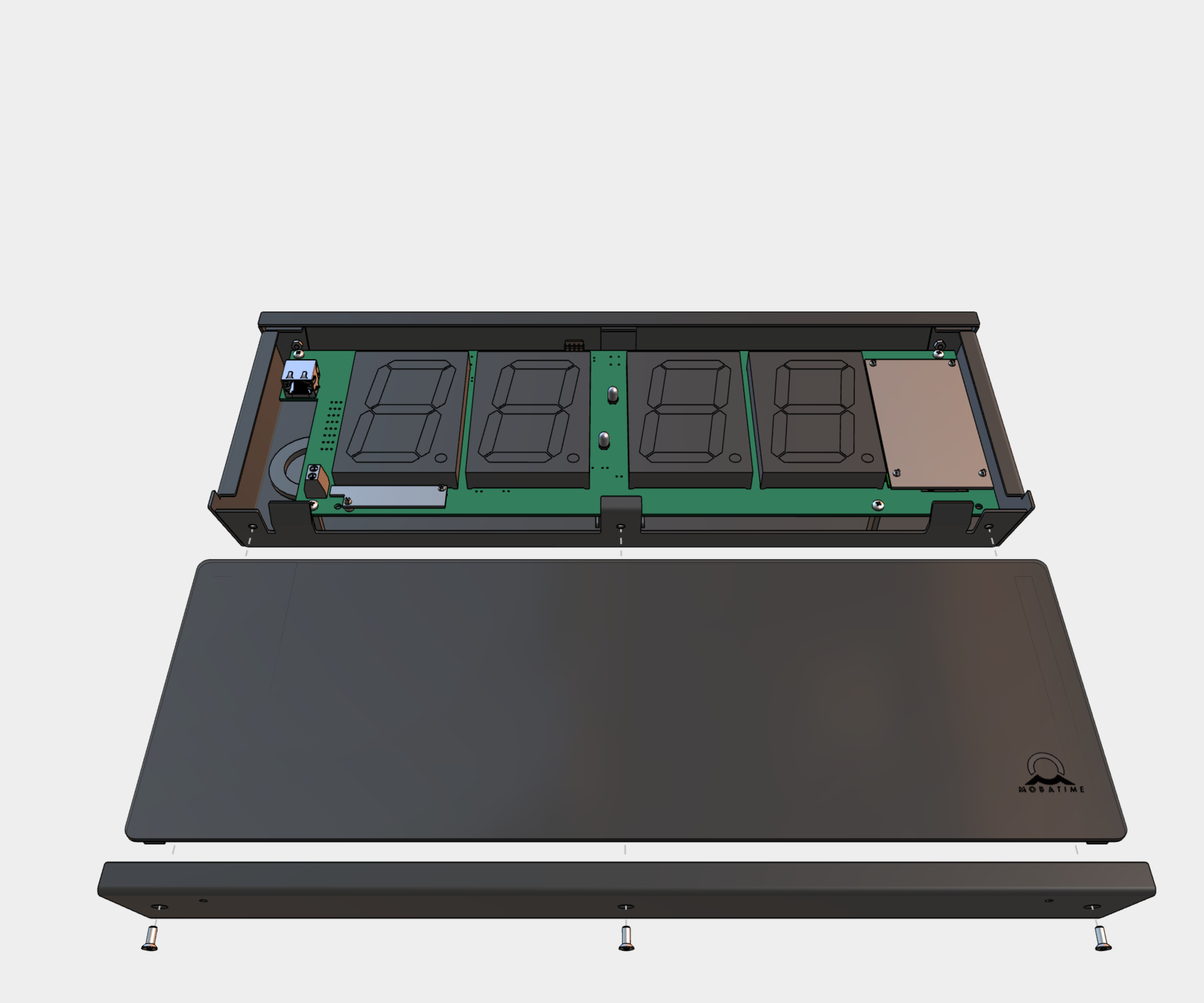
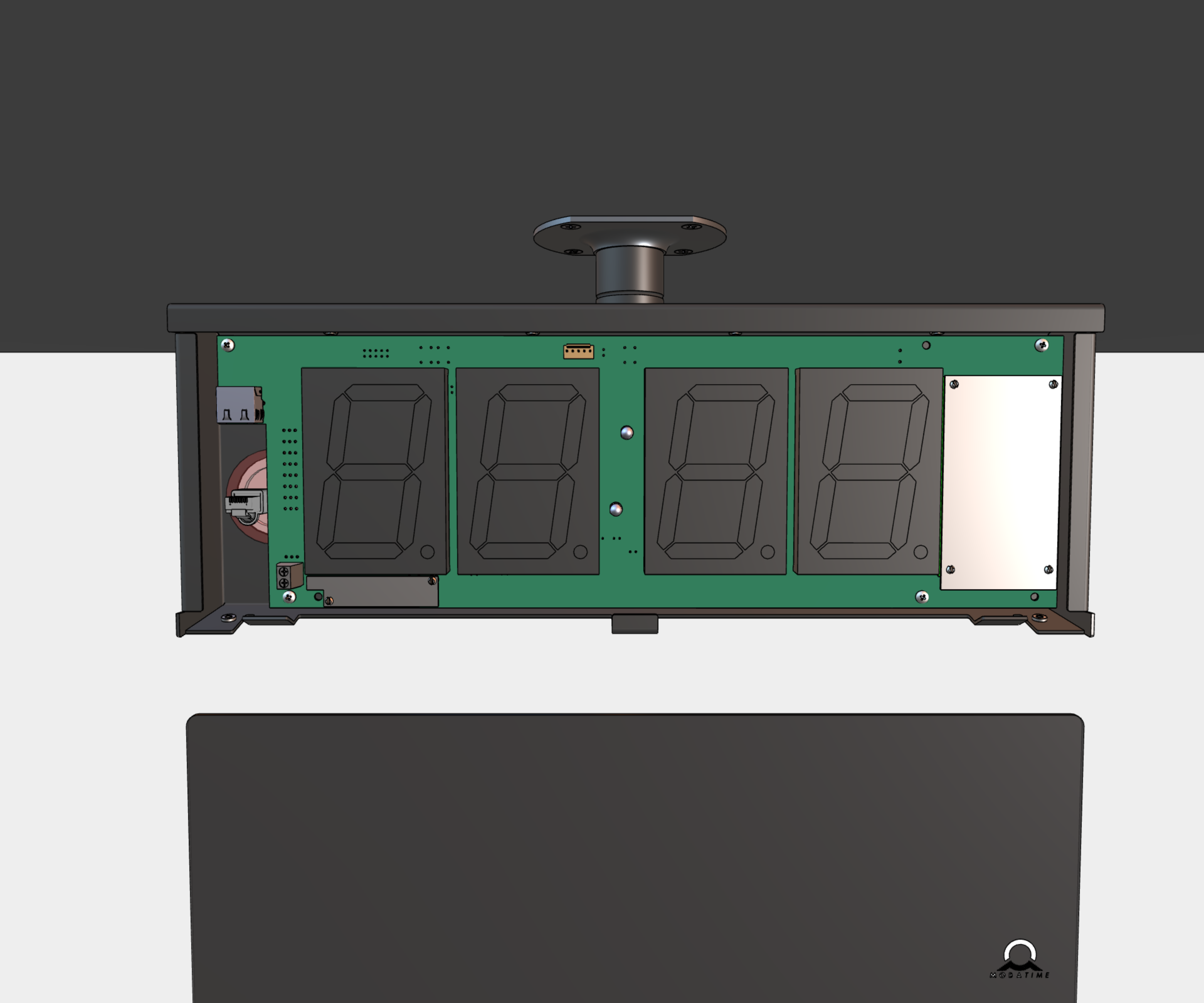
Step 3 – Remove Plexiglass#
Remove four screws on bottom of the clock. Remove the bottom cover and plexiglass.
Step 4 – Prepare & Connect Cables#
Shorten all incoming cables appropriately.
Thread cable(s) through grommet and hang the both parts (MASTER and SLAVE) onto the anchoring plate.
Except PoE variant, mount a power cable of at least 3 x 0.75 mm² (double isolation), maximal 3 x 1.5 mm² (double isolation).
Mount a 2-pin connector to synchronization signal cable or crimp RJ45 modular connector to incoming Ethernet cable.
Cut cable(s) to appropriate length and connect the wires to corresponding terminals or crimp the RJ45 jack to Ethernet cable respectively.
1
See Cable Connection chapter.
Caution
For use of a DCF/GPS receiver, make sure to switch the DIP switch accordingly.
Navigate to Clock Operation chapter > Non-Network Clock Operation chapter to get detailed info about connection of various synchronization sources and receivers.
Caution
Connect cable from SLAVE display to MASTER display.
Step 5 – Mount Back the Plexiglass#
Mount back the plexiglass and bottom cover.
The installation is complete.