Wall Mounting#
Note
Displayed numbers do not correspond with step numbers below.
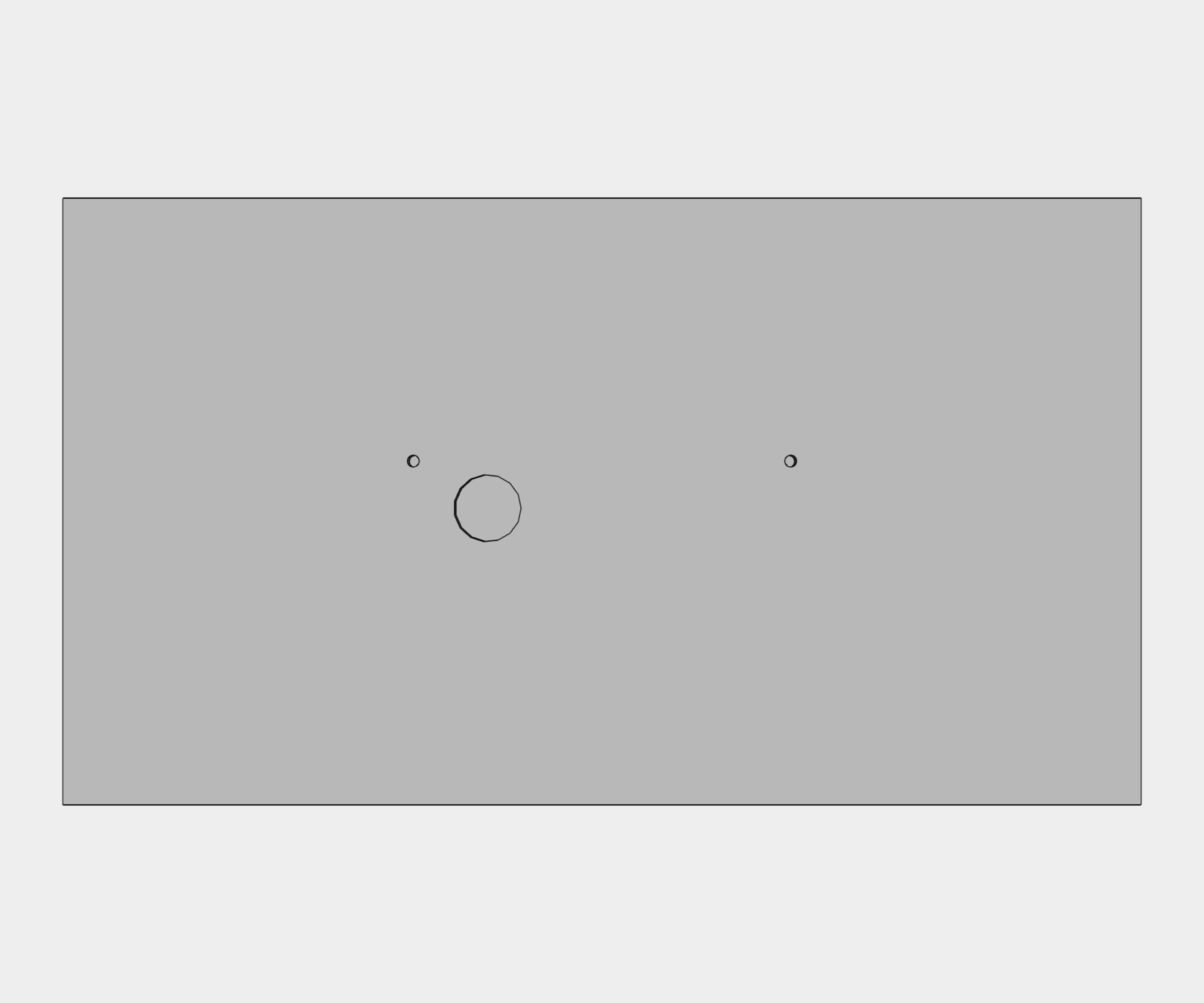
Step 1 – Prepare Mounting Holes#
Drill two anchoring holes into a wall of a diameter adequate to accommodate supplied wood-type screws with dowels. See the assembly diagram for appropriate hole spacing.
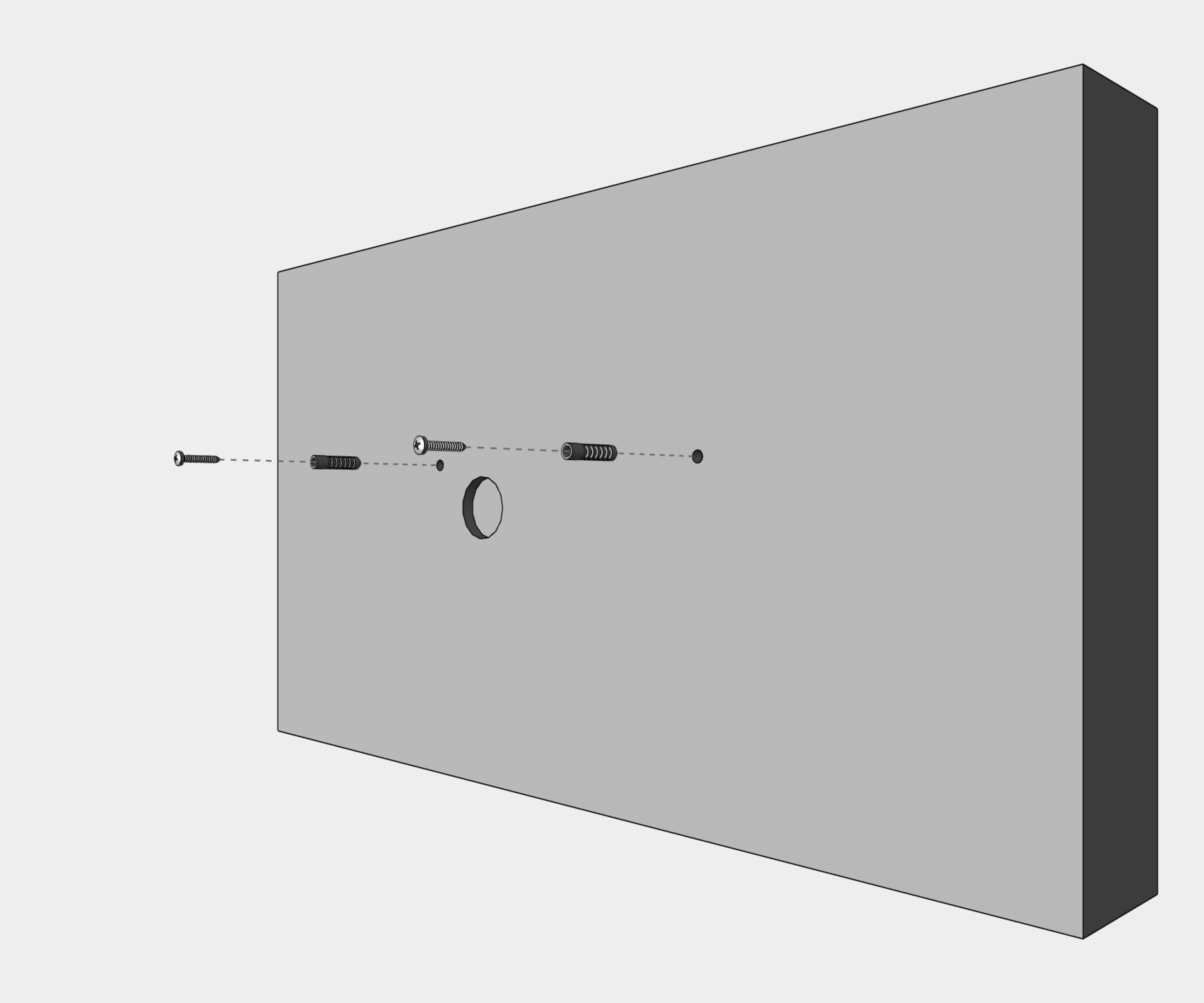
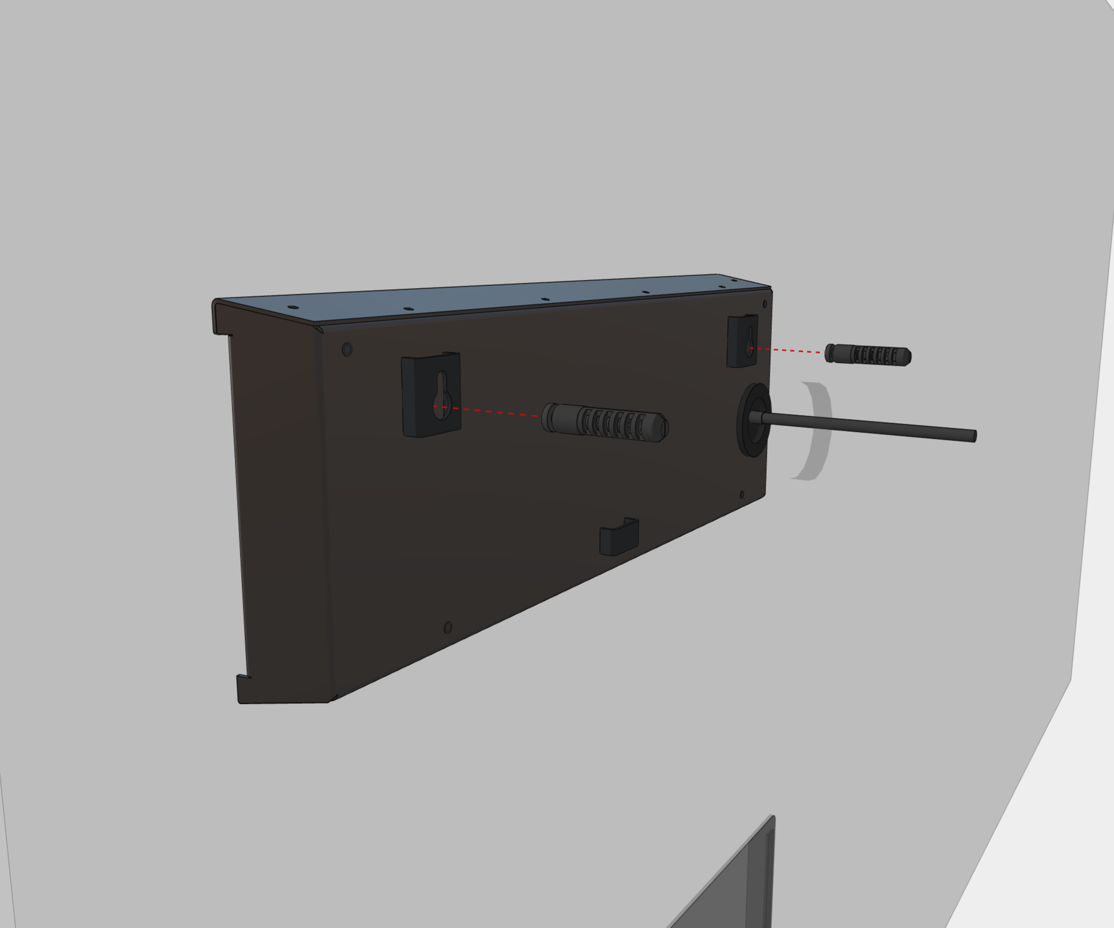
Step 2 – Prepare Mounting Screws#
Insert dowels to prepared holes and screw appropriate screws into them.
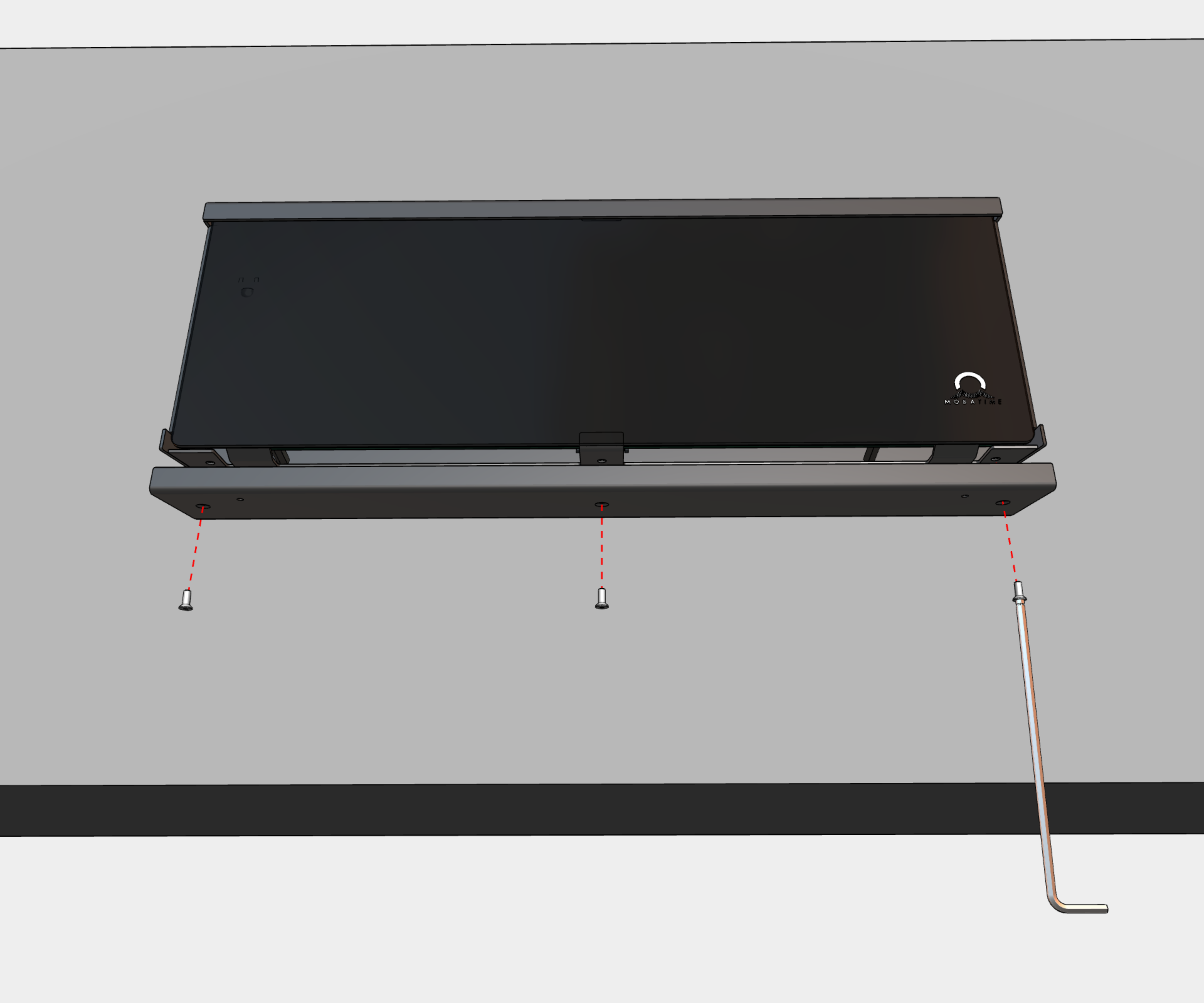
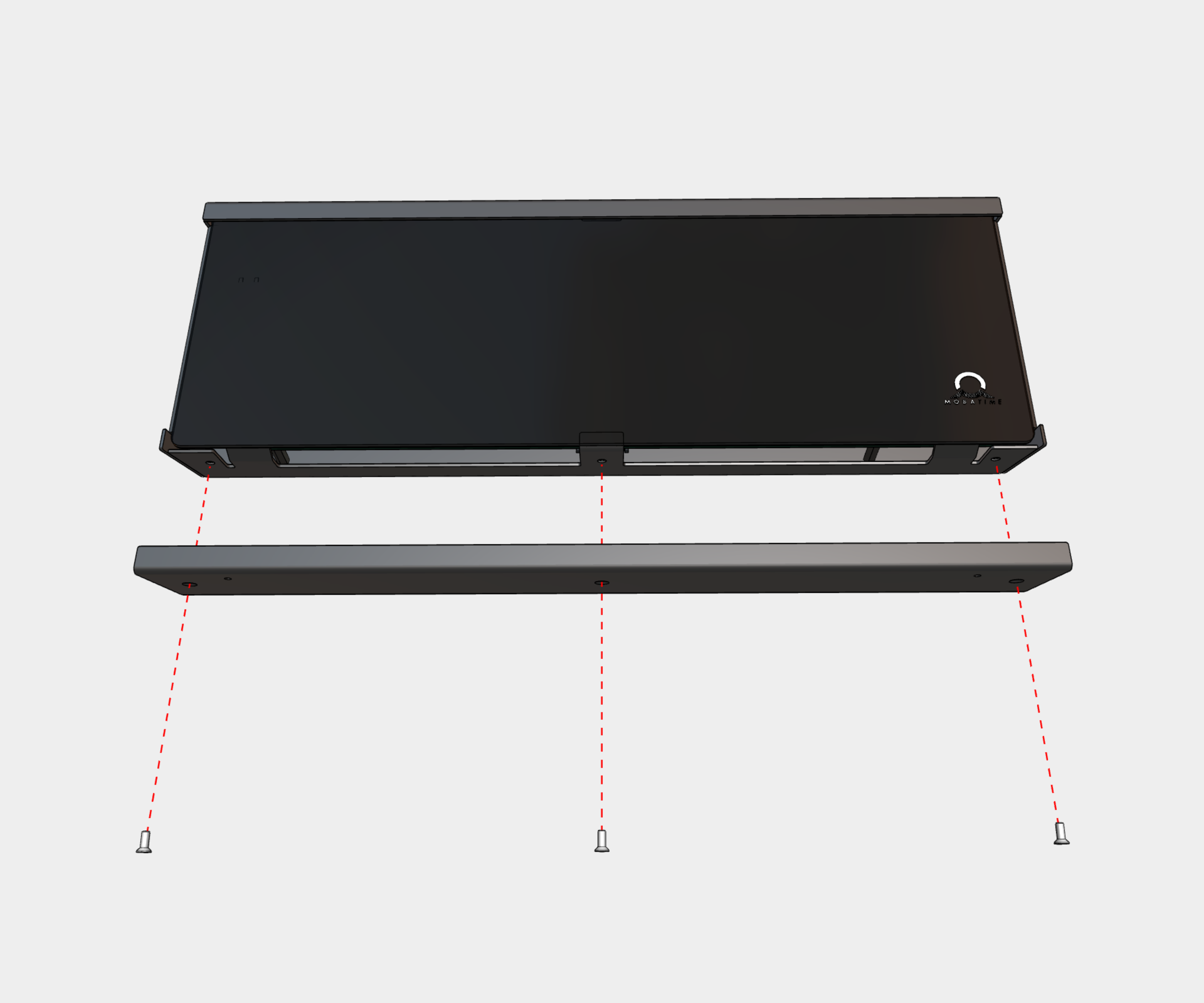
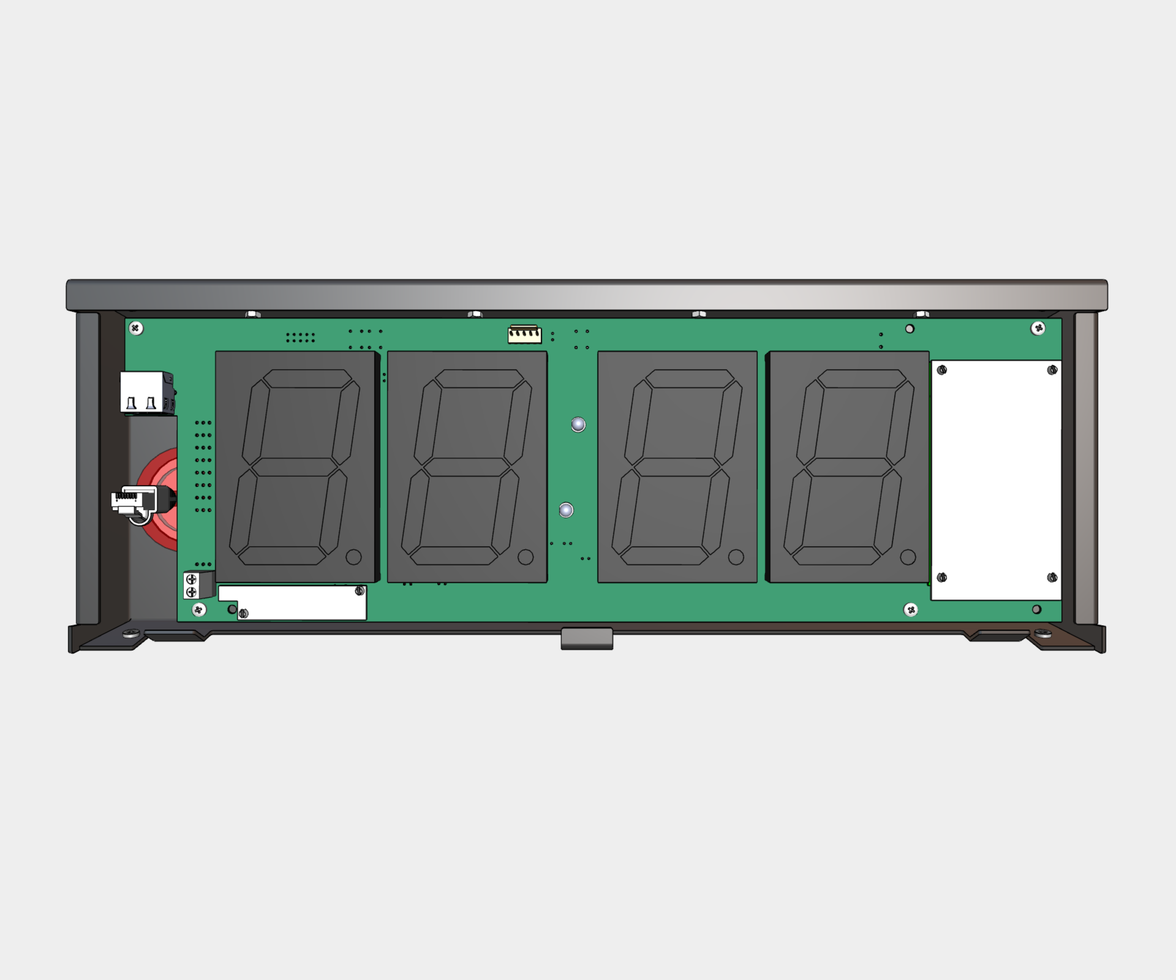
Step 3 – Remove Plexiglass#
Remove four screws on bottom of the clock. Remove the bottom cover and plexiglass.
Step 4 – Prepare & Connect Cables#
Shorten all incoming cables appropriately.
Thread cable(s) through grommet and hang the clock on prepared screws in the wall.
Except PoE variant, mount a power cable of at least 3 x 0.75 mm² (double isolation), maximal 3 x 1.5 mm² (double isolation).
Mount a 2-pin connector to synchronization signal cable or crimp RJ45 modular connector to incoming Ethernet cable.
Cut cable(s) to appropriate length and connect the wires to corresponding terminals or crimp the RJ45 jack to Ethernet cable respectively.
1
See Cable Connection chapter.
Caution
For use of a DCF/GPS receiver, make sure to switch the DIP switch accordingly.
Navigate to Clock Operation chapter > Non-Network Clock Operation chapter to get detailed info about connection of various synchronization sources and receivers.
Step 5 – Mount Back the Plexiglass#
Mount back the plexiglass and bottom cover.
The installation is complete.