

Wall Mounting#
Step 1
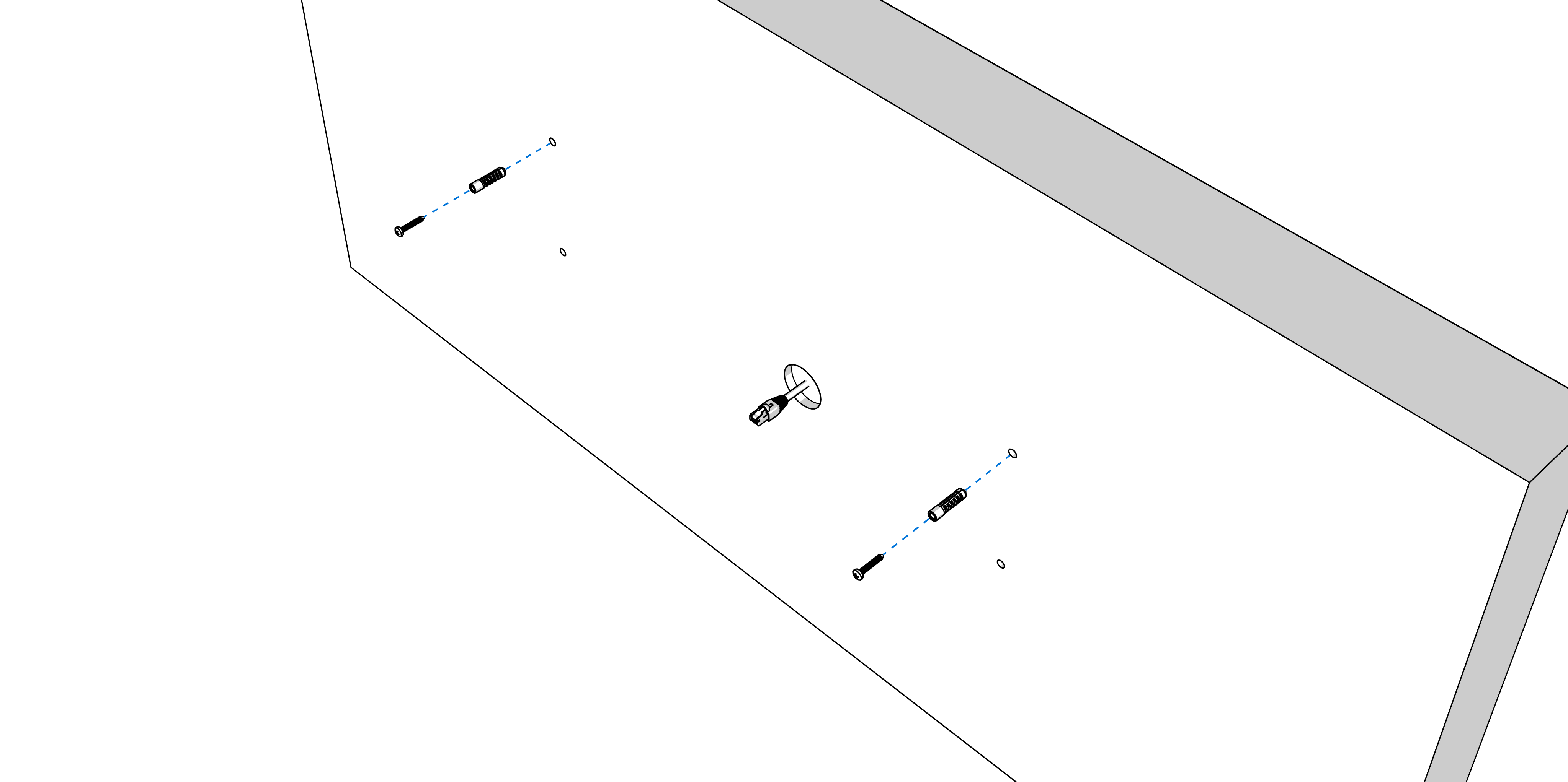
Drill appropriate number of anchoring holes into the wall of a diameter adequate to accommodate appropriate screws of 4 to 5 mm diameter. Use dowels if necessary.
Insert the wall plugs into the prepared holes and screw in the screws, leaving the screw heads at least 3 mm proud of the wall.
Step 2
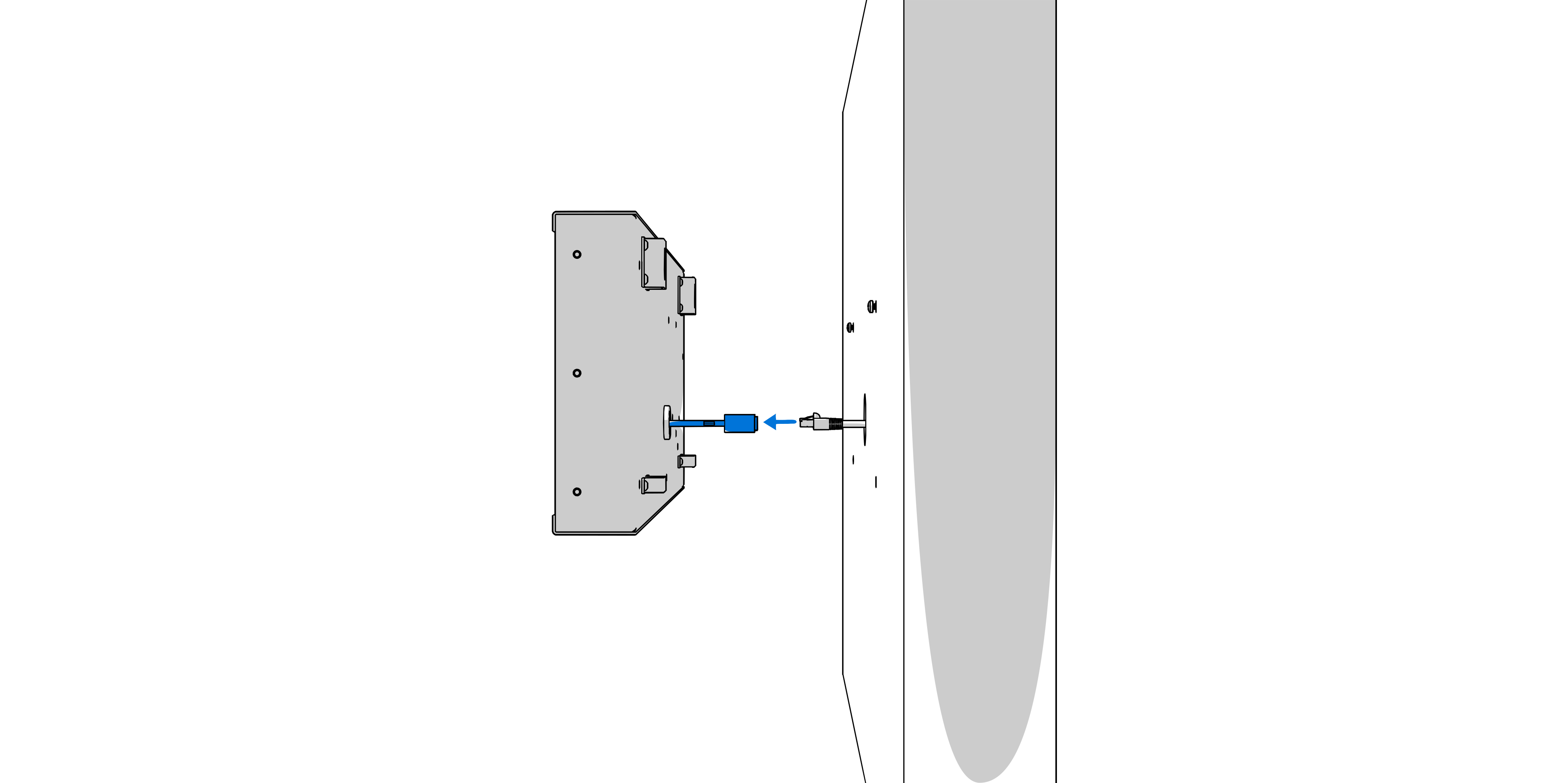
Connect all incoming cables to the pigtail lead from the clock.
Step 3
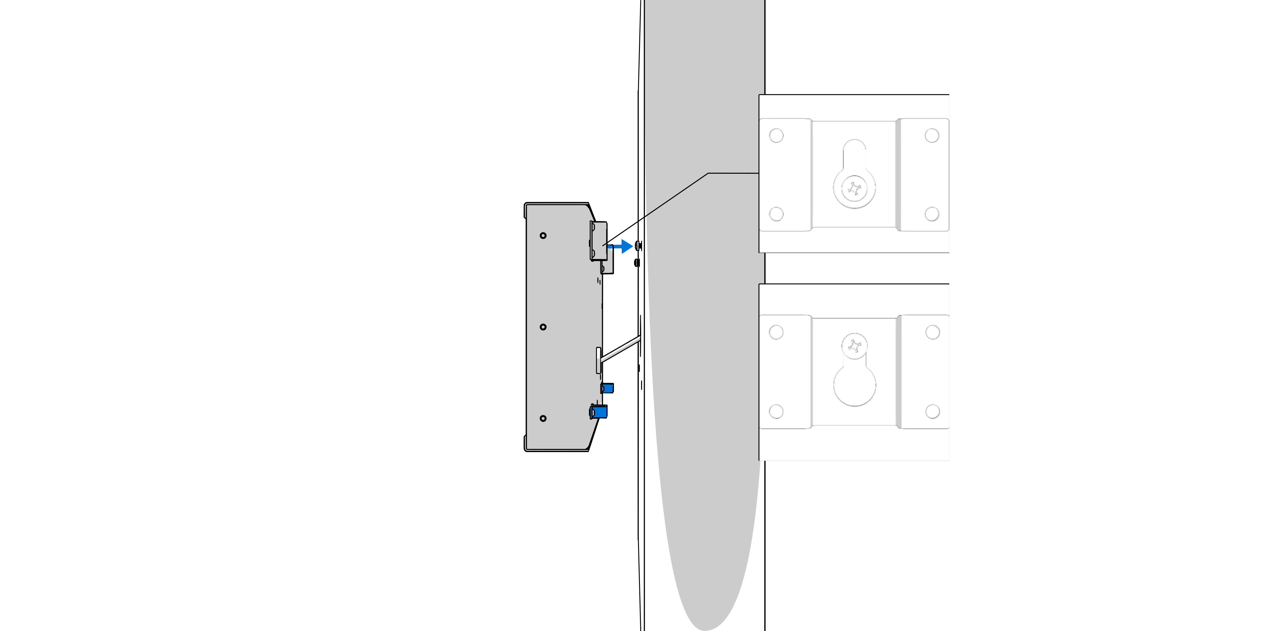
Hang the clock on the prepared screws in the wall.
Hint
If the clock has to be tilted down slightly, remove the supporting element (marked by blue) on bottom of back side accordingly.
Removing Glass#
If you need to connect other components (additional keyboards, temperature sensors, etc.) or configure the DIP switch, you need to remove the bottom cover and glass.
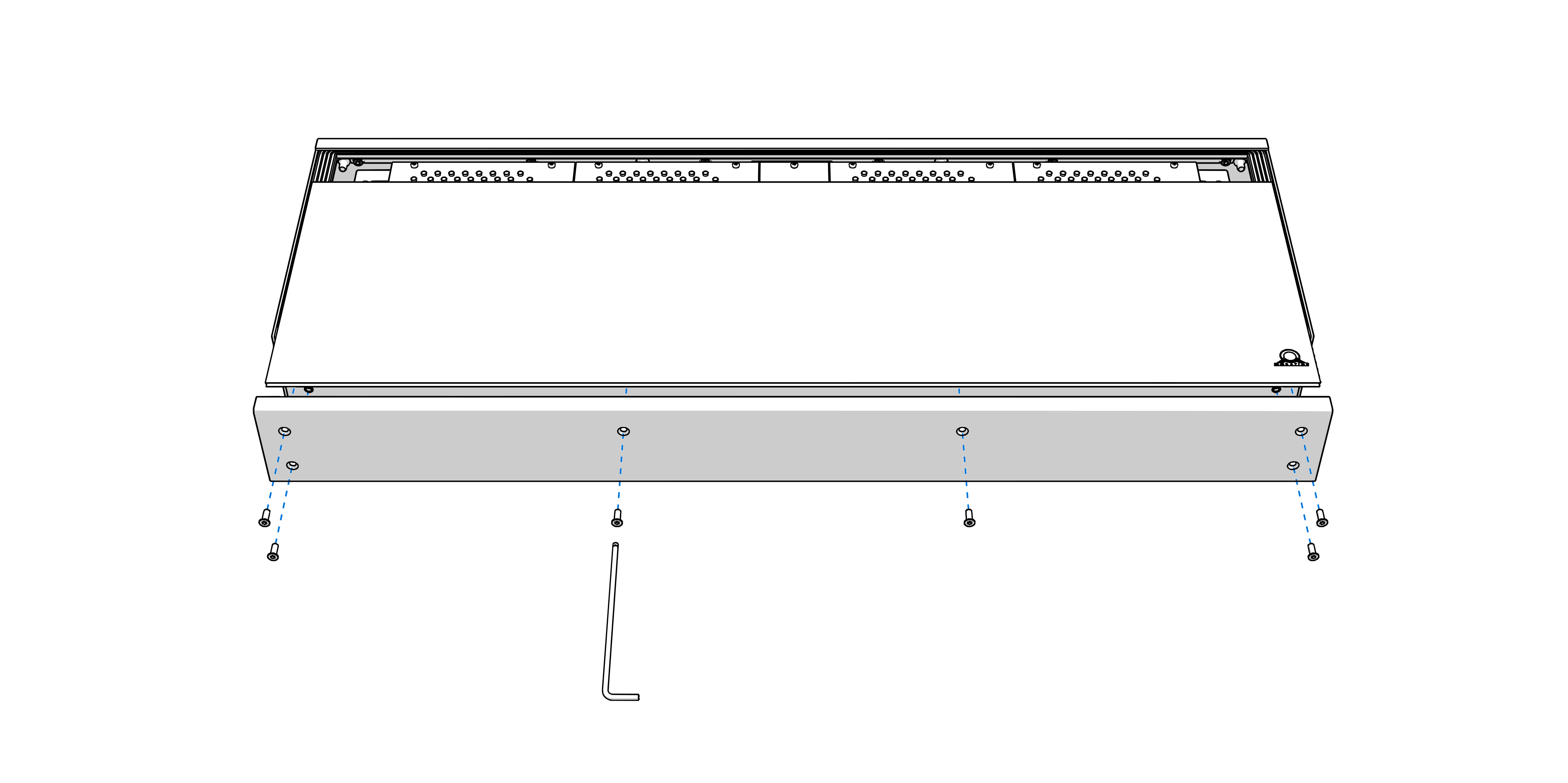
Remove the screws on the bottom side of the clock. Remove bottom cover and glass.
Thread the incoming cables through the grommet on the back side of the clock.
Connect the wires of the respective components to the terminal block on control board according to the label.
1
See chapter Cable Connection.
After connecting components or configuring the DIP switch, use reverse procedure and mount back the glass and bottom cover.